ELECTRONIC SHIFT LEVER SYSTEM, Diagnostic DTC:P1C8A49
| DTC Code | DTC Name |
|---|---|
| P1C8A49 | Park Pawl Motor Control System (Learning Value of Shift Immovable Scope) Internal Electronic Failure |
DESCRIPTION
Refer to the description for DTC P1C8949.
| DTC No. | Detection Item | DTC Detection Condition | Trouble Area | Warning Indicate |
|---|---|---|---|---|
| P1C8A49 | Park Pawl Motor Control System (Leaning Value of Shift Immovable Scope) Internal Electronic Failure | When the power switch is on (IG), and while the shift state is being changed between park (P) and a shift state other than park (P), the power supply voltage is low, an open or short occurs in the P CON MTR relay, P CON MTR2 relay, shift control actuator assembly (parking lock motor and rotation angle sensor) or wire harness, and an internal malfunction occurs in the shift control actuator assembly (parking lock motor and rotation angle sensor) continuously for 1 second or more (1 trip detection logic) |
|
|
CONFIRMATION DRIVING PATTERN
Tech Tips
After repairs have been completed, clear the DTCs and then check that the vehicle has returned to normal by performing the All Readiness check procedure.
-
Turn the power switch on (IG).
-
Depress the brake pedal and move the shift lever to select neutral (N).
-
Push the P position switch (shift position indicator) to select park (P).
CAUTION / NOTICE / HINT
Note
-
After turning the power switch off, waiting time may be required before disconnecting the cable from the negative (-) auxiliary battery terminal. Therefore, make sure to read the disconnecting the cable from the negative (-) auxiliary battery terminal notices before proceeding with work.
-
The vehicle is equipped with a sub-battery. Therefore, ensure there is no power being supplied to the vehicle when disconnecting or reconnecting the connector of the shift control ECU and when removing or installing the shift control ECU.
-
Inspect the fuses for circuits related to this system before performing the following inspection procedure.
PROCEDURE
-
CHECK DTC OUTPUT (HYBRID CONTROL)
-
Connect the GTS to the DLC3.
-
Turn the power switch on (IG).
-
Enter the following menus: Powertrain / Hybrid Control / Trouble Codes.
Powertrain > Hybrid Control > Trouble Codes -
Check if DTCs are output.
Result Result Proceed to None of the DTCs in the table below are output. A Any of the DTCs in the table below are output. B Priority Relevant DTC 1 P085D94 Gear Shift Control Module "A" Unexpected Operation P1761A2 Gear Shift Control Module "A" System Voltage Low P1765A2 Sub Battery Module System Voltage Low P176D12 IG2 Signal (Gear Shift Control Module "A") Circuit Short to Auxiliary Battery P176949 Gear Shift Control Module "A" Internal Electronic Failure 2 P1C8F14 Park Pawl Motor Phase U Circuit Short to Ground or Open P1C9414 Park Pawl Motor Phase V Circuit Short to Ground or Open P1C9914 Park Pawl Motor Phase W Circuit Short to Ground or Open Tech Tips
The chart above is listed in inspection order of priority.
-
Turn the power switch off.
B 
GO TO DTC CHART Click here
A 
-
-
CHECK FREEZE FRAME DATA (BATT VOLTAGE FOR GEAR SHIFT CONTROL MODULE)
-
Connect the GTS to the DLC3.
-
Turn the power switch on (IG).
Tech Tips
It may not be possible to turn the power switch on (READY).
-
Enter the following menus: Powertrain / Hybrid Control / Trouble Codes.
Powertrain > Hybrid Control > Trouble Codes -
Read the freeze frame data of DTC P1C8A49.
Powertrain > Hybrid ControlTester Display BATT Voltage for Gear Shift Control Module Result Result Proceed to BATT Voltage for Gear Shift Control Module is 9 V or higher. A BATT Voltage for Gear Shift Control Module is below 9 V. B -
Turn the power switch off.
B 
CHARGE AUXILIARY BATTERY Click here
A
-
-
CHECK FREEZE FRAME DATA (PROTECTION RELAY STATUS)
-
Connect the GTS to the DLC3.
-
Turn the power switch on (IG).
Tech Tips
It may not be possible to turn the power switch on (READY).
-
Enter the following menus: Powertrain / Hybrid Control / Trouble Codes.
Powertrain > Hybrid Control > Trouble Codes -
Read the freeze frame data of DTC P1C8A49.
Body Electrical > Sub Battery ModuleTester Display Protection Relay Status -
Enter the following menus: Body Electrical / Sub Battery Module / Active Test / Protection Relay
Body Electrical > Sub Battery Module > Active TestActive Test Display Protection Relay Data List Display Sub Battery Module Voltage -
Using the Dual Data List function in the GTS, read the Data List item "Sub Battery Module Voltage" during the Active Test (protection relay ON).
Result Result Proceed to The freeze frame data item "Protection Relay Status" is ON and the "Sub Battery Module Voltage" is 9 V or higher while the Active Test is being performed (protection relay ON) A The freeze frame data item "Protection Relay Status" is ON and the "Sub Battery Module Voltage" is below 9 V while the Active Test is being performed (protection relay ON) B The freeze frame data item "Protection Relay Status" is OFF C -
Turn the power switch off.
B
CHECK SUB BATTERY SYSTEM Click here
C
GO TO STEP 8 Click here
A
-
-
CLEAR DTC
-
Connect the GTS to the DLC3.
-
Turn the power switch on (IG).
-
Enter the following menus: Powertrain / Hybrid Control / Trouble Codes.
Powertrain > Hybrid Control > Trouble Codes -
Check for DTCs and freeze frame data and then write them down.
Tech Tips
When DTCs are cleared, the freeze frame data is also cleared. The freeze frame data stored when the DTCs are detected is required for troubleshooting. Therefore, check and record the stored DTC information before clearing them.
-
Clear the DTCs.
Powertrain > Hybrid Control > Clear DTCs -
Turn the power switch off.
-
Disconnect the GTS from the DLC3.
-
Leave the vehicle as is for 60 seconds or more.
Note
-
Do not connect the GTS.
-
Do not depress brake pedal.
-
Do not open/close any of the doors.
Result Proceed to NEXT -
NEXT
-
-
CHARGE AUXILIARY BATTERY
-
Charge the auxiliary battery.
Result Proceed to NEXT
NEXT
-
-
CHECK DTC OUTPUT (SIMULATION TEST)
-
Turn the power switch on (READY).
-
Depress the brake pedal and move the shift lever as follows to select each shift state: N → D.
-
Drive the vehicle at 40 km/h (25 mph) or more for 10 seconds or more.
-
Stop the vehicle and push the P position switch (shift position indicator) to select park (P).
-
Turn the power switch off.
-
Connect the GTS to the DLC3.
-
Turn the power switch on (IG) and wait for 10 seconds or more.
Tech Tips
It may not be possible to turn the power switch on (READY).
-
Depress the brake pedal and move the shift lever to select neutral (N).
-
Push the P position switch (shift position indicator) to select park (P).
-
Enter the following menus: Powertrain / Hybrid Control / Trouble Codes.
Powertrain > Hybrid Control > Trouble Codes -
Check if DTCs are output.
Result Result Proceed to Only DTC P1C8A49 is output. A None of the DTCs are output. B DTCs other than P1C8A49 are also output C -
Turn the power switch off.
B
END (AUXILIARY BATTERY WAS INSUFFICIENTLY CHARGED)
C
GO TO DTC CHART Click here
A
-
-
CHECK FREEZE FRAME DATA (PARKING LOCK MOTOR MAIN RELAY STATUS, PARKING LOCK MOTOR BACKUP RELAY STATUS)
-
Connect the GTS to the DLC3.
-
Turn the power switch on (IG).
-
Enter the following menus: Powertrain / Hybrid Control / Trouble Codes.
Powertrain > Hybrid Control > Trouble Codes -
Read the freeze frame data of DTC P1C8A49.
Powertrain > Hybrid ControlTester Display Parking Lock Motor Main Relay Status Parking Lock Motor Backup Relay Status Result Result Proceed to Parking Lock Motor Main Relay Status is ON. A Parking Lock Motor Backup Relay Status is ON. B -
Turn the power switch off.
B
CHECK FREEZE FRAME DATA (U, V, W VOLTAGE) Click here
A
-
-
CHECK FREEZE FRAME DATA (U, V, W VOLTAGE)
-
Connect the GTS to the DLC3.
-
Turn the power switch on (IG).
-
Enter the following menus: Powertrain / Hybrid Control / Trouble Codes.
Powertrain > Hybrid Control > Trouble Codes -
Read the freeze frame data of DTC P1C8A49.
Powertrain > Hybrid ControlTester Display W Phase Parking Lock Motor Terminal Voltage V Phase Parking Lock Motor Terminal Voltage U Phase Parking Lock Motor Terminal Voltage Result Tester Display Specified Condition W Phase Parking Lock Motor Terminal Voltage 1 to 2 V V Phase Parking Lock Motor Terminal Voltage 1 to 2 V U Phase Parking Lock Motor Terminal Voltage 1 to 2 V -
Turn the power switch off.
Result Proceed to OK NG
NG
CHECK HARNESS AND CONNECTOR (P CON MTR RELAY POWER SOURCE CIRCUIT) Click here
OK
-
-
CHECK HARNESS AND CONNECTOR (SHIFT CONTROL ECU - ROTATION ANGLE SENSOR (SHIFT CONTROL ACTUATOR ASSEMBLY))
-
Disconnect the A53 shift control ECU connector.
-
Disconnect the G41 rotation angle sensor (shift control actuator assembly) connector.
-
Measure the resistance according to the value(s) in the table below.
Standard Resistance (Check for Open) Tester Connection Condition Specified Condition A53-22(VC) - G41-10(RVC) Always Below 1 Ω A53-23(RA) - G41-5(RA) Always Below 1 Ω A53-21(RB) - G41-3(RB) Always Below 1 Ω A53-24(E2) - G41-8(RE2) Always Below 1 Ω Standard Resistance (Check for Short) Tester Connection Condition Specified Condition A53-22(VC) or G41-10(RVC) - Body ground and other terminals Always 10 kΩ or higher A53-23(RA) or G41-5(RA) - Body ground and other terminals Always 10 kΩ or higher A53-21(RB) or G41-3(RB) - Body ground and other terminals Always 10 kΩ or higher A53-24(E2) or G41-8(RE2) - Body ground and other terminals Always 10 kΩ or higher -
Reconnect the G41 rotation angle sensor (shift control actuator assembly) connector.
-
Reconnect the A53 shift control ECU connector.
Result Proceed to OK NG
NG
REPAIR OR REPLACE HARNESS OR CONNECTOR
OK
-
-
CHECK HARNESS AND CONNECTOR (SHIFT CONTROL ECU - BODY GROUND)
-
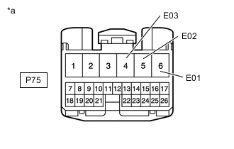
*a Front view of wire harness connector
(to Shift Control ECU)
Disconnect the shift control ECU connector.
-
Measure the resistance according to the value(s) in the table below.
Standard Resistance (Check for Open) Tester Connection Condition Specified Condition P75-6(E01) - Body ground Always Below 1 Ω P75-5(E02) - Body ground Always Below 1 Ω P75-4(E03) - Body ground Always Below 1 Ω -
Reconnect the shift control ECU connector.
Result Proceed to OK NG
NG
REPAIR OR REPLACE HARNESS OR CONNECTOR
OK
-
-
CHECK SHIFT CONTROL ACTUATOR ASSEMBLY
-
Check that the parking brake is applied.
-
Pull the shift control actuator assembly from the hybrid vehicle transmission assembly.
-
Reconnect the G41 shift control actuator assembly connector.
-
Release the brake pedal and turn the power switch on (ACC).
Note
The shift control actuator assembly may operate if the power switch is turned on (IG) or on (READY). Do not turn the power switch on (IG) or on (READY) during this inspection to prevent the shift control actuator assembly from operating while in contact with the splines.
-
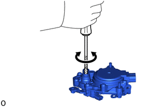
Using a screwdriver with its tip wrapped with protective tape or a piece of cloth, rotate the shaft.
Note
-
During this inspection, make sure to use a screwdriver with its tip wrapped with protective tape or a piece of cloth to prevent the splines of the actuator from being damaged.
-
Rotate the shaft with torque of 2 N*m (20.3 kgf*cm, 17.7 in.*lbf) or less. Do not apply load while the contacting the stopper inside the actuator.
-
The shift control actuator assembly cannot be disassembled.
-
Confirm that the shaft of the shift control actuator assembly rotates smoothly.
OK The shaft of the shift control actuator assembly rotates smoothly. -
Measure the voltage according to the value(s) in the table below.
Note
When measuring the voltage, turn the shift control actuator assembly slowly.
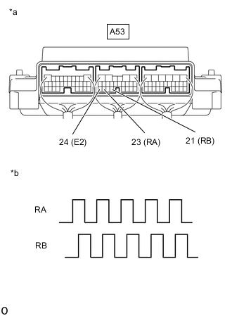
*a Component with harness connected
(Shift Control ECU)
*b Output Waveform while Splines of Shift Control Actuator Assembly being Rotated (Example) Standard Voltage Tester Connection Condition Specified Condition A53-23(RA) - A53-24(E2) Power switch on (ACC), shaft of shift control actuator assembly being rotated 0 to 1.5 V ←→ 4 to 5.5 V A53-21(RB) - A53-24(E2) Power switch on (ACC), shaft of shift control actuator assembly being rotated 0 to 1.5 V ←→ 4 to 5.5 V
-
-
Turn the power switch off.
Result Proceed to OK NG
NG
REPLACE SHIFT CONTROL ACTUATOR ASSEMBLY Click here
OK
-
-
CHECK ROTATION ANGLE SENSOR (SHIFT CONTROL ACTUATOR ASSEMBLY)
-
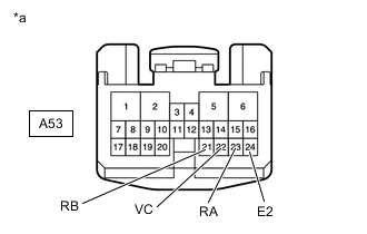
*a Front view of wire harness connector
(to Shift Control ECU)
Disconnect the shift control ECU connector.
-
Measure the resistance according to the value(s) in the table below.
Standard Resistance Tester Connection Switch Condition Specified Condition A53-22(VC) - A53-23(RA) Power switch off 10 kΩ or higher A53-22(VC) - A53-21(RB) Power switch off 10 kΩ or higher A53-22(VC) - A53-24(E2) Power switch off 590 to 670 Ω A53-23(RA) - A53-21(RB) Power switch off 10 kΩ or higher A53-23(RA) - A53-24(E2) Power switch off 10 kΩ or higher A53-21(RB) - A53-24(E2) Power switch off 10 kΩ or higher -
Reconnect the shift control ECU connector.
Result Proceed to OK NG
NG
REPLACE SHIFT CONTROL ACTUATOR ASSEMBLY Click here
OK
-
-
CHECK HYBRID VEHICLE TRANSMISSION ASSEMBLY
-
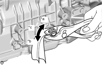
*a Lock *b Unlock *c Rotate approximately 20° Wrap the shaft with a piece of cloth and turn it using pliers.
OK The shaft rotates smoothly in the lock and unlock directions. Note
-
Rotate the shaft using torque between 4.0 and 7.0 N*m (41 and 71 kgf*cm, 36 and 61 in.*lbf).
-
During this inspection, make sure to use a piece of cloth to prevent the shaft splines from being damaged.
-
-
Set the shaft in the lock position after the inspection.
Result Proceed to OK NG
OK
REPLACE SHIFT CONTROL ECU Click here
NG
REPLACE HYBRID VEHICLE TRANSMISSION ASSEMBLY Click here
-
-
CHARGE AUXILIARY BATTERY
-
Charge the auxiliary battery.
Result Proceed to NEXT
NEXT
-
-
CLEAR DTC
-
Connect the GTS to the DLC3.
-
Turn the power switch on (IG).
-
Enter the following menus: Powertrain / Hybrid Control / Trouble Codes.
Powertrain > Hybrid Control > Trouble Codes -
Check for DTCs and freeze frame data and then write them down.
-
Clear the DTCs.
Powertrain > Hybrid Control > Clear DTCs -
Turn the power switch off.
-
Disconnect the GTS from the DLC3.
-
Leave the vehicle as is for 60 seconds or more.
Note
-
Do not connect the GTS.
-
Do not depress brake pedal.
-
Do not open/close any of the doors.
Result Proceed to NEXT -
NEXT
-
-
CHECK DTC OUTPUT (SIMULATION TEST)
-
Turn the power switch on (READY).
-
Depress the brake pedal and move the shift lever as follows to select each shift state: N → D.
-
Drive the vehicle at 40 km/h (25 mph) or more for 10 seconds or more.
-
Stop the vehicle and push the P position switch (shift position indicator) to select park (P).
-
Turn the power switch off.
-
Connect the GTS to the DLC3.
-
Turn the power switch on (IG) and wait for 10 seconds or more.
Tech Tips
It may not be possible to turn the power switch on (READY).
-
Depress the brake pedal and move the shift lever to select neutral (N).
-
Push the P position switch (shift position indicator) to select park (P).
-
Enter the following menus: Powertrain / Hybrid Control / Trouble Codes.
Powertrain > Hybrid Control > Trouble Codes -
Check if DTCs are output.
Result Result Proceed to None of the DTCs are output. A Only DTC P1C8A49 is output. B DTCs other than P1C8A49 are also output C -
Turn the power switch off.
A
END
B
REPLACE AUXILIARY BATTERY Click here
C
GO TO DTC CHART Click here
-
-
CHECK HARNESS AND CONNECTOR (P CON MTR RELAY POWER SOURCE CIRCUIT)
-
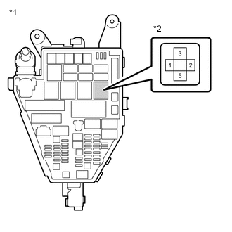
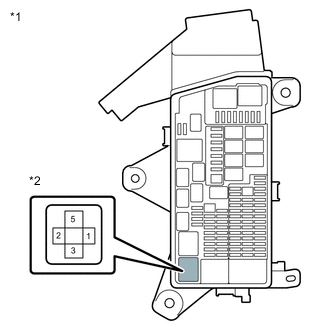
*1 No. 1 Engine Room Relay Block and Junction Block Assembly *2 P CON MTR Relay Remove the P CON MTR relay from the No. 1 engine room relay block and junction block assembly
-
Measure the voltage according to the value(s) in the table below.
Standard Voltage Tester Connection Switch Condition Specified Condition P CON MTR relay terminal 3 or 2 - Body ground Power switch off 8 to 15.4 V -
Install the P CON MTR relay.
Result Proceed to OK NG
NG
CHECK HARNESS AND CONNECTOR (AUXILIARY BATTERY - P CON MTR RELAY) Click here
OK
-
-
INSPECT P CON MTR RELAY
-
*1 No. 1 Engine Room Relay Block and Junction Block Assembly *2 P CON MTR Relay Remove the P CON MTR relay from the No. 1 engine room relay block and junction block assembly
-
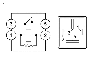
*1 P CON MTR Relay Measure the resistance according to the value(s) in the table below.
Standard Resistance Tester Connection Condition Specified Condition 3 - 5 Auxiliary battery voltage not applied between terminals 1 and 2 10 kΩ or higher Auxiliary battery voltage applied between terminals 1 and 2 Below 1 Ω -
Install the P CON MTR relay.
Result Proceed to OK NG
NG
REPLACE P CON MTR RELAY
OK
-
-
CHECK HARNESS AND CONNECTOR (PARKING LOCK MOTOR (SHIFT CONTROL ACTUATOR ASSEMBLY) - P CON MTR RELAY - SHIFT CONTROL ECU)
-
Disconnect the G41 parking lock motor (shift control actuator assembly) connector.
-
Remove the P CON MTR relay from the No. 1 engine room relay block and junction block assembly.
-
Disconnect the A53 shift control ECU connector.
-
Measure the resistance according to the value(s) in the table below.
Standard Resistance (Check for Open) Tester Connection Condition Specified Condition P CON MTR relay terminal 5 - G41-7(BMA) Always Below 1 Ω P CON MTR relay terminal 1 - A53-12(BMA1) Always Below 1 Ω Standard Resistance (Check for Short) Tester Connection Condition Specified Condition P CON MTR relay terminal 5 or G41-7(BMA) - Body ground and other terminals (except P CON MTR2 relay terminal 5) Always 10 kΩ or higher P CON MTR relay terminal 1 or A53-12(BMA1) - Body ground and other terminals Always 10 kΩ or higher -
Reconnect the A53 shift control ECU connector.
-
Install the P CON MTR relay.
-
Reconnect the G41 parking lock motor (shift control actuator assembly) connector.
Result Proceed to OK NG
NG
REPAIR OR REPLACE HARNESS OR CONNECTOR
OK
-
-
CHECK HARNESS AND CONNECTOR (SHIFT CONTROL ECU - PARKING LOCK MOTOR (SHIFT CONTROL ACTUATOR ASSEMBLY))
-
Disconnect the A53 shift control ECU connector.
-
Disconnect the G41 parking lock motor (shift control actuator assembly) connector.
-
Measure the resistance according to the value(s) in the table below.
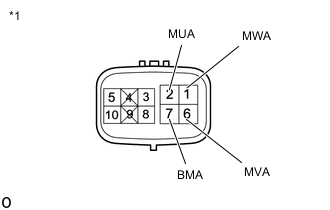
Standard Resistance (Check for Open) Tester Connection Condition Specified Condition A53-5(MUA) - G41-2(MUA) Always Below 1 Ω A53-2(MVA) - G41-6(MVA) Always Below 1 Ω A53-1(MWA) - G41-1(MWA) Always Below 1 Ω Standard Resistance (Check for Short) Tester Connection Condition Specified Condition A53-5(MUA) or G41-2(MUA) - Body ground and other terminals Always 10 kΩ or higher A53-2(MVA) or G41-6(MVA) - Body ground and other terminals Always 10 kΩ or higher A53-1(MWA) or G41-1(MWA) - Body ground and other terminals Always 10 kΩ or higher -
Reconnect the G41 parking lock motor (shift control actuator assembly) connector.
-
Reconnect the A53 shift control ECU connector.
Result Proceed to OK NG
NG
REPAIR OR REPLACE HARNESS OR CONNECTOR
OK
-
-
INSPECT PARKING LOCK MOTOR (SHIFT CONTROL ACTUATOR ASSEMBLY)
-
*1 Parking Lock Motor (Shift Control Actuator Assembly) Disconnect the parking lock motor (shift control actuator assembly) connector.
-
Measure the resistance according to the value(s) in the table below.
Standard Resistance (Check for Open) Tester Connection Condition Specified Condition 2(MUA) - 7(BMA) Always 0.5 to 2 Ω 6(MVA) - 7(BMA) Always 0.5 to 2 Ω 1(MWA) - 7(BMA) Always 0.5 to 2 Ω 2(MUA) - 6(MVA) Always 1 to 4 Ω 6(MVA) - 1(MWA) Always 1 to 4 Ω 1(MWA) - 2(MUA) Always 1 to 4 Ω Standard Resistance (Check for Short) Tester Connection Condition Specified Condition 2(MUA) - Body ground Always 10 kΩ or higher 6(MVA) - Body ground Always 10 kΩ or higher 1(MWA) - Body ground Always 10 kΩ or higher -
Reconnect the parking lock motor (shift control actuator assembly) connector.
Result Proceed to OK NG
OK
REPLACE SHIFT CONTROL ECU Click here
NG
REPLACE SHIFT CONTROL ACTUATOR ASSEMBLY Click here
-
-
CHECK HARNESS AND CONNECTOR (AUXILIARY BATTERY - P CON MTR RELAY)
-
Disconnect the cable from the negative (-) auxiliary battery terminal.
-
Disconnect the cable from the positive (+) auxiliary battery terminal.
-
Remove the P CON MTR relay from the No. 1 engine room relay block and junction block assembly.
-
Measure the resistance according to the value(s) in the table below.
Standard Resistance (Check for Open) Tester Connection Condition Specified Condition Auxiliary battery positive (+) cable - P CON MTR relay terminal 3 or 2 Always Below 1 Ω Standard Resistance (Check for Short) Tester Connection Condition Specified Condition Auxiliary battery positive (+) cable or P CON MTR relay terminal 3 or 2 - Body ground and other terminals Always 10 kΩ or higher -
Install the P CON MTR relay.
-
Reconnect the cable to the positive (+) auxiliary battery terminal.
-
Reconnect the cable to the negative (-) auxiliary battery terminal.
Result Proceed to OK NG
NG
REPAIR OR REPLACE HARNESS OR CONNECTOR
OK
-
-
CHARGE AUXILIARY BATTERY
-
Charge the auxiliary battery.
Result Proceed to NEXT
NEXT
-
-
CLEAR DTC
-
Connect the GTS to the DLC3.
-
Turn the power switch on (IG).
-
Enter the following menus: Powertrain / Hybrid Control / Trouble Codes.
Powertrain > Hybrid Control > Trouble Codes -
Check for DTCs and freeze frame data and then write them down.
-
Clear the DTCs.
Powertrain > Hybrid Control > Clear DTCs -
Turn the power switch off.
-
Disconnect the GTS from the DLC3.
-
Leave the vehicle as is for 60 seconds or more.
Note
-
Do not connect the GTS.
-
Do not depress brake pedal.
-
Do not open/close any of the doors.
Result Proceed to NEXT -
NEXT
-
-
CHECK DTC OUTPUT (SIMULATION TEST)
-
Turn the power switch on (READY).
-
Depress the brake pedal and move the shift lever as follows to select each shift state: N → D.
-
Drive the vehicle at 40 km/h (25 mph) or more for 10 seconds or more.
-
Stop the vehicle and push the P position switch (shift position indicator) to select park (P).
-
Turn the power switch off.
-
Connect the GTS to the DLC3.
-
Turn the power switch on (IG) and wait for 10 seconds or more.
Tech Tips
It may not be possible to turn the power switch on (READY).
-
Depress the brake pedal and move the shift lever to select neutral (N).
-
Push the P position switch (shift position indicator) to select park (P).
-
Enter the following menus: Powertrain / Hybrid Control / Trouble Codes.
Powertrain > Hybrid Control > Trouble Codes -
Check if DTCs are output.
Result Result Proceed to None of the DTCs are output. A Only DTC P1C8A49 is output. B DTCs other than P1C8A49 are also output C -
Turn the power switch off.
A
END
B
REPLACE AUXILIARY BATTERY Click here
C
GO TO DTC CHART Click here
-
-
CHECK FREEZE FRAME DATA (U, V, W VOLTAGE)
-
Connect the GTS to the DLC3.
-
Turn the power switch on (IG).
-
Enter the following menus: Powertrain / Hybrid Control / Trouble Codes.
Powertrain > Hybrid Control > Trouble Codes -
Read the freeze frame data of DTC P1C8A49.
Powertrain > Hybrid ControlTester Display W Phase Parking Lock Motor Terminal Voltage V Phase Parking Lock Motor Terminal Voltage U Phase Parking Lock Motor Terminal Voltage Result Tester Display Specified Condition W Phase Parking Lock Motor Terminal Voltage 1 to 2 V V Phase Parking Lock Motor Terminal Voltage 1 to 2 V U Phase Parking Lock Motor Terminal Voltage 1 to 2 V -
Turn the power switch off.
Result Proceed to OK NG
OK
GO TO STEP 9 Click here
NG
-
-
CHECK HARNESS AND CONNECTOR (P CON MTR RELAY POWER SOURCE CIRCUIT)
-
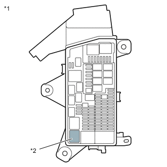
*1 No. 1 Engine Room Relay Block and Junction Block Assembly *2 P CON MTR Relay Remove the P CON MTR relay from the No. 1 engine room relay block and junction block assembly.
-
Measure the voltage according to the value(s) in the table below.
Standard Voltage Tester Connection Switch Condition Specified Condition P CON MTR relay terminal 3 or 2 - Body ground Power switch off 8 to 15.4 V -
Install the P CON MTR relay.
Result Proceed to OK NG
NG
CHECK HARNESS AND CONNECTOR (AUXILIARY BATTERY - P CON MTR RELAY) Click here
OK
-
-
INSPECT P CON MTR RELAY
-
*1 No. 1 Engine Room Relay Block and Junction Block Assembly *2 P CON MTR Relay Remove the P CON MTR relay from the No. 1 engine room relay block and junction block assembly.
-
*1 P CON MTR Relay Measure the resistance according to the value(s) in the table below.
Standard Resistance Tester Connection Condition Specified Condition 3 - 5 Auxiliary battery voltage not applied between terminals 1 and 2 10 kΩ or higher Auxiliary battery voltage applied between terminals 1 and 2 Below 1 Ω -
Install the P CON MTR relay.
Result Proceed to OK NG
NG
REPLACE P CON MTR RELAY Click here
OK
-
-
CHECK HARNESS AND CONNECTOR (PARKING LOCK MOTOR (SHIFT CONTROL ACTUATOR ASSEMBLY) - P CON MTR RELAY - SHIFT CONTROL ECU)
-
Disconnect the G41 parking lock motor (shift control actuator assembly) connector.
-
Remove the P CON MTR relay from the No. 1 engine room relay block and junction block assembly.
-
Disconnect the A53 shift control ECU connector.
-
Measure the resistance according to the value(s) in the table below.
Standard Resistance (Check for Open) Tester Connection Condition Specified Condition P CON MTR relay terminal 5 - G41-7(BMA) Always Below 1 Ω P CON MTR relay terminal 1 - A53-12(BMA1) Always Below 1 Ω Standard Resistance (Check for Short) Tester Connection Condition Specified Condition P CON MTR relay terminal 5 or G41-7(BMA) - Body ground and other terminals (except P CON MTR2 relay terminal 5) Always 10 kΩ or higher P CON MTR relay terminal 1 or A53-12(BMA1) - Body ground and other terminals Always 10 kΩ or higher -
Reconnect the A53 shift control ECU connector.
-
Install the P CON MTR relay.
-
Reconnect the G41 parking lock motor (shift control actuator assembly) connector.
Result Proceed to OK NG
NG
REPAIR OR REPLACE HARNESS OR CONNECTOR Click here
OK
-
-
CHECK HARNESS AND CONNECTOR (SHIFT CONTROL ECU - PARKING LOCK MOTOR (SHIFT CONTROL ACTUATOR ASSEMBLY))
-
Disconnect the A53 shift control ECU connector.
-
Disconnect the G41 parking lock motor (shift control actuator assembly) connector.
-
Measure the resistance according to the value(s) in the table below.
Standard Resistance (Check for Open) Tester Connection Condition Specified Condition A53-5(MUA) - G41-2(MUA) Always Below 1 Ω A53-2(MVA) - G41-6(MVA) Always Below 1 Ω A53-1(MWA) - G41-1(MWA) Always Below 1 Ω Standard Resistance (Check for Short) Tester Connection Condition Specified Condition A53-5(MUA) or G41-2(MUA) - Body ground and other terminals Always 10 kΩ or higher A53-2(MVA) or G41-6(MVA) - Body ground and other terminals Always 10 kΩ or higher A53-1(MWA) or G41-1(MWA) - Body ground and other terminals Always 10 kΩ or higher -
Reconnect the G41 parking lock motor (shift control actuator assembly) connector.
-
Reconnect the A53 shift control ECU connector.
Result Proceed to OK NG
NG
REPAIR OR REPLACE HARNESS OR CONNECTOR Click here
OK
-
-
CHECK HARNESS AND CONNECTOR (P CON MTR2 RELAY POWER SOURCE CIRCUIT)
-
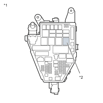
*1 No. 2 Luggage Room Relay Block Assembly *2 P CON MTR2 Relay Remove the P CON MTR2 relay from the No. 2 luggage room relay block assembly.
-
Turn the power switch on (IG).
-
Measure the voltage according to the value(s) in the table below.
Standard Voltage Tester Connection Condition Specified Condition P CON MTR2 relay terminal 3 or 2 - Body ground 5 seconds after turning the power switch on (IG) 8 to 15.4 V Note
Power is supplied from the sub-battery module assembly for only 5 seconds after the power switch is turned on (IG). Therefore, measure the voltage during that time.
-
Turn the power switch off.
-
Install the P CON MTR2 relay.
Result Proceed to OK NG
NG
CHECK HARNESS AND CONNECTOR (SUB-BATTERY MODULE ASSEMBLY - P CON MTR2 RELAY) Click here
OK
-
-
INSPECT P CON MTR2 RELAY
-
*1 No. 2 Luggage Room Relay Block Assembly *2 P CON MTR2 Relay Remove the P CON MTR2 relay from the No. 2 luggage room relay block assembly.
-
*1 P CON MTR2 Relay Measure the resistance according to the value(s) in the table below.
Standard Resistance Tester Connection Condition Specified Condition 3 - 5 Auxiliary battery voltage not applied between terminals 1 and 2 10 kΩ or higher Auxiliary battery voltage applied between terminals 1 and 2 Below 1 Ω -
Install the P CON MTR2 relay.
Result Proceed to OK NG
NG
REPLACE P CON MTR2 RELAY
OK
-
-
CHECK HARNESS AND CONNECTOR (PARKING LOCK MOTOR (SHIFT CONTROL ACTUATOR ASSEMBLY) - P CON MTR2 RELAY - SHIFT CONTROL ECU)
-
Disconnect the G41 parking lock motor (shift control actuator assembly) connector.
-
Remove the P CON MTR2 relay from the No. 2 luggage room relay block assembly.
-
Disconnect the P74 shift control ECU connector.
-
Measure the resistance according to the value(s) in the table below.
Standard Resistance (Check for Open) Tester Connection Condition Specified Condition P CON MTR2 relay terminal 5 - G41-7(BMA) Always Below 1 Ω P CON MTR2 relay terminal 1 - P74-24(BMA2) Always Below 1 Ω Standard Resistance (Check for Short) Tester Connection Condition Specified Condition P CON MTR2 relay terminal 5 or G41-7(BMA) - Body ground and other terminals (except P CON MTR relay terminal 5) Always 10 kΩ or higher P CON MTR2 relay terminal 1 or P74-24(BMA2) - Body ground and other terminals Always 10 kΩ or higher -
Reconnect the P74 shift control ECU connector.
-
Install the P CON MTR2 relay.
-
Reconnect the G41 parking lock motor (shift control actuator assembly) connector.
Result Proceed to OK NG
NG
REPAIR OR REPLACE HARNESS OR CONNECTOR
OK
-
-
CHECK HARNESS AND CONNECTOR (SHIFT CONTROL ECU - PARKING LOCK MOTOR (SHIFT CONTROL ACTUATOR ASSEMBLY))
-
Disconnect the A53 shift control ECU connector.
-
Disconnect the G41 parking lock motor (shift control actuator assembly) connector.
-
Measure the resistance according to the value(s) in the table below.
Standard Resistance (Check for Open) Tester Connection Condition Specified Condition A53-5(MUA) - G41-2(MUA) Always Below 1 Ω A53-2(MVA) - G41-6(MVA) Always Below 1 Ω A53-1(MWA) - G41-1(MWA) Always Below 1 Ω Standard Resistance (Check for Short) Tester Connection Condition Specified Condition A53-5(MUA) or G41-2(MUA) - Body ground and other terminals Always 10 kΩ or higher A53-2(MVA) or G41-6(MVA) - Body ground and other terminals Always 10 kΩ or higher A53-1(MWA) or G41-1(MWA) - Body ground and other terminals Always 10 kΩ or higher -
Reconnect the G41 parking lock motor (shift control actuator assembly) connector.
-
Reconnect the A53 shift control ECU connector.
Result Proceed to OK NG
NG
REPAIR OR REPLACE HARNESS OR CONNECTOR
OK
-
-
INSPECT PARKING LOCK MOTOR (SHIFT CONTROL ACTUATOR ASSEMBLY)
-
*1 Parking Lock Motor (Shift Control Actuator Assembly) Disconnect the parking lock motor (shift control actuator assembly) connector.
-
Measure the resistance according to the value(s) in the table below.
Standard Resistance (Check for Open) Tester Connection Condition Specified Condition 2(MUA) - 7(BMA) Always 0.5 to 2 Ω 6(MVA) - 7(BMA) Always 0.5 to 2 Ω 1(MWA) - 7(BMA) Always 0.5 to 2 Ω 2(MUA) - 6(MVA) Always 1 to 4 Ω 6(MVA) - 1(MWA) Always 1 to 4 Ω 1(MWA) - 2(MUA) Always 1 to 4 Ω Standard Resistance (Check for Short) Tester Connection Condition Specified Condition 2(MUA) - Body ground Always 10 kΩ or higher 6(MVA) - Body ground Always 10 kΩ or higher 1(MWA) - Body ground Always 10 kΩ or higher -
Reconnect the parking lock motor (shift control actuator assembly) connector.
Result Proceed to OK NG
OK
REPLACE SHIFT CONTROL ECU Click here
NG
REPLACE SHIFT CONTROL ACTUATOR ASSEMBLY Click here
-
-
REPLACE P CON MTR RELAY
Result Proceed to NEXT
NEXT
GO TO STEP 42 Click here
-
CHECK HARNESS AND CONNECTOR (AUXILIARY BATTERY - P CON MTR RELAY)
-
Disconnect the cable from the negative (-) auxiliary battery terminal.
-
Disconnect the cable from the positive (+) auxiliary battery terminal.
-
Remove the P CON MTR relay from the No. 1 engine room relay block and junction block assembly.
-
Measure the resistance according to the value(s) in the table below.
Standard Resistance (Check for Open) Tester Connection Condition Specified Condition Auxiliary battery positive (+) cable - P CON MTR relay terminal 3 or 2 Always Below 1 Ω Standard Resistance (Check for Short) Tester Connection Condition Specified Condition Auxiliary battery positive (+) cable or P CON MTR relay terminal 3 or 2 - Body ground and other terminals Always 10 kΩ or higher -
Install the P CON MTR relay.
-
Reconnect the cable to the positive (+) auxiliary battery terminal.
-
Reconnect the cable to the negative (-) auxiliary battery terminal.
Result Proceed to OK NG
NG
REPAIR OR REPLACE HARNESS OR CONNECTOR Click here
OK
-
-
CHARGE AUXILIARY BATTERY
-
Charge the auxiliary battery.
Result Proceed to NEXT
NEXT
-
-
CLEAR DTC
-
Connect the GTS to the DLC3.
-
Turn the power switch on (IG).
-
Enter the following menus: Powertrain / Hybrid Control / Trouble Codes.
Powertrain > Hybrid Control > Trouble Codes -
Check for DTCs and freeze frame data and then write them down.
-
Clear the DTCs.
Powertrain > Hybrid Control > Clear DTCs -
Turn the power switch off.
-
Disconnect the GTS from the DLC3.
-
Leave the vehicle as is for 60 seconds or more.
Note
-
Do not connect the GTS.
-
Do not depress brake pedal.
-
Do not open/close any of the doors.
Result Proceed to NEXT -
NEXT
-
-
CHECK DTC OUTPUT (SIMULATION TEST)
-
Turn the power switch on (READY).
-
Depress the brake pedal and move the shift lever as follows to select each shift state: N → D.
-
Drive the vehicle at 40 km/h (25 mph) or more for 10 seconds or more.
-
Stop the vehicle and push the P position switch (shift position indicator) to select park (P).
-
Turn the power switch off.
-
Connect the GTS to the DLC3.
-
Turn the power switch on (IG) and wait for 10 seconds or more.
Tech Tips
It may not be possible to turn the power switch on (READY).
-
Depress the brake pedal and move the shift lever to select neutral (N).
-
Push the P position switch (shift position indicator) to select park (P).
-
Enter the following menus: Powertrain / Hybrid Control / Trouble Codes.
Powertrain > Hybrid Control > Trouble Codes -
Check if DTCs are output.
Result Result Proceed to None of the DTCs are output. A Only DTC P1C8A49 is output. B DTCs other than P1C8A49 are also output C -
Turn the power switch off.
A
END
B
REPLACE AUXILIARY BATTERY Click here
C
GO TO DTC CHART Click here
-
-
REPAIR OR REPLACE HARNESS OR CONNECTOR
Result Proceed to NEXT
NEXT
-
CLEAR DTC
-
Connect the GTS to the DLC3.
-
Turn the power switch on (IG).
-
Enter the following menus: Powertrain / Hybrid Control / Trouble Codes.
Powertrain > Hybrid Control > Trouble Codes -
Check for DTCs and freeze frame data and then write them down.
-
Clear the DTCs.
Powertrain > Hybrid Control > Clear DTCs -
Turn the power switch off.
-
Disconnect the GTS from the DLC3.
-
Leave the vehicle as is for 60 seconds or more.
Note
-
Do not connect the GTS.
-
Do not depress brake pedal.
-
Do not open/close any of the doors.
Result Proceed to NEXT -
NEXT
-
-
CHECK DTC OUTPUT (SIMULATION TEST)
-
Turn the power switch on (READY).
-
Depress the brake pedal and move the shift lever as follows to select each shift state: N → D.
-
Drive the vehicle at 40 km/h (25 mph) or more for 10 seconds or more.
-
Stop the vehicle and push the P position switch (shift position indicator) to select park (P).
-
Turn the power switch off.
-
Connect the GTS to the DLC3.
-
Turn the power switch on (IG) and wait for 10 seconds or more.
Tech Tips
It may not be possible to turn the power switch on (READY).
-
Depress the brake pedal and move the shift lever to select neutral (N).
-
Push the P position switch (shift position indicator) to select park (P).
-
Enter the following menus: Powertrain / Hybrid Control / Trouble Codes.
Powertrain > Hybrid Control > Trouble Codes -
Check if DTCs are output.
Result Result Proceed to None of the DTCs are output. A Only DTC P1C8A49 is output. B DTCs other than P1C8A49 are also output C -
Turn the power switch off.
A
END
B
GO TO STEP 31 Click here
C
GO TO DTC CHART Click here
-
-
CHECK HARNESS AND CONNECTOR (SUB-BATTERY MODULE ASSEMBLY - P CON MTR2 RELAY)
-
Disconnect the b7 positive (+) terminal from the sub-battery module assembly.
-
Remove the P CON MTR2 relay from the No. 2 luggage room relay block assembly.
-
Measure the resistance according to the value(s) in the table below.
Standard Resistance (Check for Open) Tester Connection Condition Specified Condition b7-1(+BAT) - P CON MTR2 relay terminal 3 or 2 Always Below 1 Ω Standard Resistance (Check for Short) Tester Connection Condition Specified Condition b7-1(+BAT) or P CON MTR2 relay terminal 3 or 2 - Body ground and other terminals Always 10 kΩ or higher -
Install the P CON MTR2 relay.
-
Reconnect the b7 positive (+) terminal to the sub-battery module assembly.
Result Proceed to OK NG
OK
CHECK SUB BATTERY SYSTEM Click here
NG
REPAIR OR REPLACE HARNESS OR CONNECTOR
-
-
REPAIR OR REPLACE HARNESS OR CONNECTOR
Result Proceed to NEXT
NEXT
GO TO STEP 42 Click here
-
REPAIR OR REPLACE HARNESS OR CONNECTOR
Result Proceed to NEXT
NEXT
GO TO STEP 42 Click here