RADIATOR INSTALLATION
PROCEDURE
-
INSTALL NO. 5 RADIATOR TO SUPPORT SEAL
-
Install a new No. 5 radiator support to seal to the radiator assembly.
-
-
INSTALL NO. 4 RADIATOR TO SUPPORT SEAL
-
Install a new No. 4 radiator support to seal to the radiator assembly.
-
-
INSTALL NO. 3 RADIATOR TO SUPPORT SEAL
-
Install a new No. 3 radiator support to seal to the radiator assembly.
-
-
INSTALL NO. 2 RADIATOR TO SUPPORT SEAL
-
Install a new No. 2 radiator support to seal to the radiator assembly.
-
-
INSTALL NO. 1 RADIATOR TO SUPPORT SEAL
-
Install 2 new No. 1 radiator support to seals to the radiator assembly.
-
-
INSTALL LOWER RADIATOR SUPPORT
-
Install the 2 lower radiator supports to the radiator assembly.
-
-
INSTALL RADIATOR SUPPORT CUSHION
-
Install the 2 radiator support cushions to the radiator assembly.
-
-
INSTALL FAN WITH MOTOR ASSEMBLY
-
Attach the 2 guides.
-
Install the fan with motor assembly to the radiator assembly with the 2 bolts.
Note
Do not damage the radiator assembly when installing the fan with motor assembly.
- Torque:
- 12 N*m { 122 kgf*cm, 9 ft.*lbf }
-
-
INSTALL NO. 2 RADIATOR HOSE
-
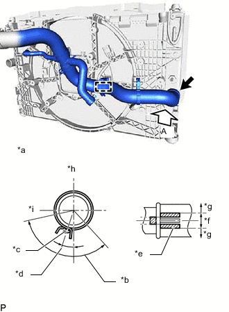
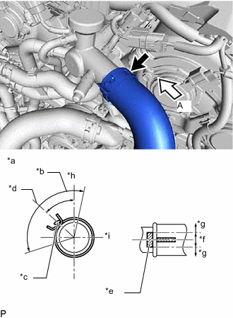
*a View A *b 120° *c Paint Mark (White) *d Claw Center Direction *e Variation Range *f OK *g NG *h Upper Side *i LH Side Install the No. 2 radiator hose to the radiator assembly, and slide the clip to secure the hose.
-
Attach the clamp to install the No. 2 radiator hose to the fan with motor assembly.
-
-
INSTALL NO. 2 INVERTER COOLING HOSE
-
Install the No. 2 inverter cooling hose to the radiator assembly with the 2 clips and clamp.
-
-
INSTALL REAR RADIATOR SIDE AIR GUIDE PLATE RH
-
Attach the 2 claws to install the rear radiator side air guide plate RH to the radiator assembly.
-
-
INSTALL DISCHARGE HOSE SUB-ASSEMBLY
-
Attach the clamp to install the discharge hose sub-assembly to the fan with motor assembly.
-
-
INSTALL NO. 1 RADIATOR HOSE
-
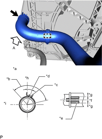
*a View A *b 120° *c Paint Mark (White) *d Claw Center Direction *e Variation Range *f OK *g NG *h Upper Side *i LH Side Install the No. 1 radiator hose to the radiator assembly, and slide the clip to secure the hose.
-
Attach the clamp to install the No. 2 radiator hose to the fan with motor assembly.
-
-
INSTALL NO. 3 INVERTER COOLING HOSE
-
Install the No. 3 inverter cooling hose to the radiator assembly with the bolt and clip.
- Torque:
- 8.0 N*m { 82 kgf*cm, 71 in.*lbf }
-
-
INSTALL REAR RADIATOR SIDE AIR GUIDE PLATE LH
-
Attach the 3 claws and install the rear radiator side air guide plate LH to the radiator assembly.
-
-
INSTALL RADIATOR ASSEMBLY
-
Install the radiator assembly together with the fan with motor assembly to the vehicle.
Note
-
Perform the following procedure with 2 or more people to prevent damage to the radiator assembly.
-
Do not damage the radiator assembly, fan with motor assembly, cooler pipe or cooling hoses when installing them.
-
-

Bolt A 
Bolt B Install the front crossmember sub-assembly with the 6 bolts.
- Torque:
- for bolt A
- 30 N*m { 306 kgf*cm, 22 ft.*lbf }
- for bolt B
- 14 N*m { 143 kgf*cm, 10 ft.*lbf }
Standard Length Item Length Bolt A 22.5 mm (0.886 in.) Bolt B 80 mm (3.15 in.) -
Attach the 2 guides.
-
Attach the 2 claws and connect the cooler condenser assembly to the radiator assembly.
Note
Do not damage the cooler condenser assembly or radiator assembly when installing the cooler condenser assembly.
-
-
CONNECT DISCHARGE HOSE SUB-ASSEMBLY
-
Connect the discharge hose sub-assembly to the cooler condenser assembly.
-
Connect the discharge hose sub-assembly to the cooler compressor assembly.
-
-
CONNECT LIQUID TUBE SUB-ASSEMBLY A
-
INSTALL HOOD LOCK SUPPORT BRACE
-
Install the hood lock support brace to the front crossmember sub-assembly with the bolt.
- Torque:
- 12.5 N*m { 127 kgf*cm, 9 ft.*lbf }
-
-
INSTALL UPPER RADIATOR SUPPORT SUB-ASSEMBLY
-
Install the upper radiator support with the 5 bolts.
- Torque:
- 12.5 N*m { 127 kgf*cm, 9 ft.*lbf }
-
-
CONNECT ENGINE ROOM MAIN WIRE
-
Connect the 3 clamps, 4 connectors and engine room main wire.
-
-
CONNECT OIL COOLER INLET HOSE
-
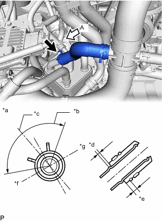
*a View A *b 120° *c Paint Mark *d 0 to 3 mm (0 to 0.118 in.) *e 2 to 7 mm (0.0787 to 0.2756 in.) *f Front Side *g Rear Side Connect the oil cooler inlet hose to the motor cooling cooler, and slide the clip to secure the hose.
Note
-
Align the paint marks on the oil cooler inlet hose to the paint mark on the motor cooling cooler.
-
The hose clamp claw position is within the range shown in the illustration.
-
Do not deform the motor cooling cooler.
-
Water or coolant can be used to assist with inserting the hose, however when using liquid other than water, dilute it to 50% concentration or less before use.
-
-
-
CONNECT TRANSMISSION OIL COOLER HOSE
-
Connect the transmission oil cooler hose to the radiator assembly, and slide the clip to secure the hose.
-
-
CONNECT NO. 3 ENGINE WIRE
-
Connect the No. 3 engine wire with the 2 bolts.
- Torque:
- 10 N*m { 102 kgf*cm, 7 ft.*lbf }
-
Attach the 2 wire harness clamps and claw.
-
-
CONNECT NO. 2 OIL COOLER OUTLET HOSE
-
Connect the No. 2 oil cooler outlet hose to the radiator assembly, and slide the clip to secure the hose.
-
-
CONNECT NO. 3 INVERTER COOLING HOSE
-
for LHD:
-
for RHD:
-
Connect the No. 3 inverter cooling hose to the radiator assembly (for inverter coolant)
-
Connect the No. 3 inverter cooling hose to the No. 5 inverter cooling hose.
Note
Secure the quick connector retainer by locking it until a "click" sound is heard.
-
-
-
CONNECT NO. 2 INVERTER COOLING HOSE
-
CONNECT NO. 2 INVERTER COOLING HOSE ASSEMBLY (for RHD)
-
Connect the No. 2 inverter cooling hose assembly to the fan with motor assembly with the 3 clamps.
-
Connect the No. 2 inverter cooling hose to the No. 4 inverter cooling hose.
Note
Secure the quick connector retainer by locking it until a "click" sound is heard.
-
-
CONNECT NO. 6 INVERTER COOLING HOSE (for LHD)
-
Connect the No. 6 inverter cooling hose to the inverter cooling inlet pipe assembly, and slide the clip to secure the hose.
-
-
CONNECT NO. 3 RADIATOR HOSE
-
Connect the No. 3 radiator hose to the water inlet with thermostat sub-assembly, and slide the clip to secure the hose.
-
-
CONNECT NO. 1 RADIATOR HOSE
-
*a View A *b 120° *c Paint Mark (Yellow) *d Claw Center Direction *e Rib *f OK *g NG *h Upper Side *i Rear Side Install the No. 1 radiator hose to the water outlet sub-assembly, and slide the clip to secure the hose.
-
-
INSTALL INVERTER WATER PUMP ASSEMBLY WITH MOTOR
-
INSTALL INVERTER RESERVE TANK ASSEMBLY
-
INSTALL RADIATOR RESERVE TANK ASSEMBLY
-
Install the radiator reserve tank assembly to the fan with motor assembly with the 2 bolts.
- Torque:
- 5.0 N*m { 51 kgf*cm, 44 in.*lbf }
-
for LHD:
-
Attach the clamp to connect the No. 3 inverter cooling hose to the radiator reserve tank assembly.
-
Connect the reserve tank outlet hose to the radiator reserve tank assembly, and slide the clip to secure the hose.
-
Install the radiator reserve tank hose, and slide the 2 clips to secure the hose.
-
-
for RHD:
-
Connect the reserve tank outlet hose, and slide the clip to secure the hose.
-
Install the radiator reserve tank hose, and slide the 2 clips to secure the hose.
-
-
Connect the 3 connectors, attach the 3 wire harness clamps to connect the engine room main wire from the radiator reserve tank assembly.
-
-
INSTALL HOOD LOCK CONTROL CABLE COVER RH
-
INSTALL HOOD LOCK CONTROL CABLE COVER LH (for LHD)
-
INSTALL HOOD LOCK ASSEMBLY
-
INSTALL HOOD LOCK RELEASE LEVER PROTECTOR
-
INSTALL LOWER ARM BRACKET BRACE SUB-ASSEMBLY RH
-
INSTALL LOWER ARM BRACKET BRACE SUB-ASSEMBLY LH
-
INSTALL RADIATOR SUPPORT OPENING COVER
-
Install the 4 screws, attach the 3 claws and install the radiator support opening cover to the front crossmember sub-assembly.
- Torque:
- 5.5 N*m { 56 kgf*cm, 49 in.*lbf }
-
-
INSTALL RADIATOR SUPPORT EXTENSION RH
-
Install the 3 screws, attach the 2 claws and install the radiator support extension RH to the radiator support opening cover.
- Torque:
- 5.5 N*m { 56 kgf*cm, 49 in.*lbf }
-
Connect the front fender liner RH to the radiator support extension RH with the 3 screws.
-
-
INSTALL RADIATOR SUPPORT EXTENSION LH
-
Install the 3 screws, attach the 2 claws and install the radiator support extension LH to the radiator support opening cover.
- Torque:
- 5.5 N*m { 56 kgf*cm, 49 in.*lbf }
-
Connect the front fender liner LH to the radiator support extension LH with the 3 screws.
-
-
INSTALL NO. 2 FRONT BUMPER REINFORCEMENT SUB-ASSEMBLY
-
Install the No. 2 front bumper reinforcement sub-assembly with the 6 nuts.
- Torque:
- 25 N*m { 255 kgf*cm, 18 ft.*lbf }
-
-
INSTALL AIR CLEANER WITH AIR CLEANER HOSE
-
INSTALL NO. 1 AIR CLEANER INLET
-
INSTALL RADIATOR SUPPORT TO CROSSMEMBER BRACE SUB-ASSEMBLY RH
-
INSTALL RADIATOR SUPPORT TO CROSSMEMBER BRACE SUB-ASSEMBLY LH
-
INSTALL FRONT BUMPER
-
ADD COOLANT (for Inverter)
-
ADD ENGINE COOLANT
-
CHARGE AIR CONDITIONING SYSTEM WITH REFRIGERANT
-
for HFC-134a(R134a):
-
for HFO-1234yf(R1234yf):
-
-
INSPECT FOR COOLANT LEAK (for Inverter)
-
INSPECT FOR COOLANT LEAK
-
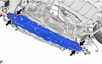
INSTALL ENGINE UNDER COVER REINFORCEMENT
-
Install the engine under cover reinforcement to the strut bar bracket support sub-assembly with the 4 bolts.
- Torque:
- 8.0 N*m { 82 kgf*cm, 71 in.*lbf }
-
-
INSTALL NO. 1 ENGINE UNDER COVER ASSEMBLY
-
INSTALL V-BANK COVER SUB-ASSEMBLY
-
INSPECT FOR COOLING FAN MOTOR