INTAKE MANIFOLD INSTALLATION
PROCEDURE
-
INSTALL STUD BOLT
Tech Tips
If a stud bolt is deformed or the threads are damaged, replace it.
-
Using an E8 "TORX" socket wrench, install the 2 stud bolts to the intake manifold.
- Torque:
- 10 N*m { 102 kgf*cm, 7 ft.*lbf }
-
-
INSTALL INTAKE MANIFOLD
-
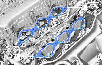
*a Protrusion Set 2 new No. 1 intake manifold to head gaskets on each cylinder head as shown in the illustration.
Note
-
Align the port holes of the gasket, cylinder head sub-assembly and cylinder head LH.
-
Be careful of the installation direction.
-
-
Set the intake manifold on the cylinder head sub-assembly and cylinder head LH.
-
Install and uniformly tighten the 4 bolts and 4 nuts.
- Torque:
- 21 N*m { 214 kgf*cm, 15 ft.*lbf }
-
-
INSTALL EGR VALVE ASSEMBLY
-
INSTALL WATER BY-PASS HOSE
-
CONNECT NO. 15 WATER BY-PASS HOSE
-
CONNECT GENERATOR CABLE AND MOTOR CABLE (for LHD)
-
INSTALL FUEL DELIVERY PIPE SUB-ASSEMBLY
-
CONNECT WIRE HARNESS
-
INSTALL FUEL TUBE SUB-ASSEMBLY
-
INSTALL NO. 1 ENGINE COVER SUB-ASSEMBLY
-
INSTALL INTAKE AIR SURGE TANK ASSEMBLY
Note
Do not apply oil to the bolts and nuts as listed below:
Oil Application Prohibited Bolt and Nut Bolt and Nut for Intake Air Surge Tank Assembly and Intake Manifold Bolt for No. 2 Surge Tank Stay and Intake Air Surge Tank Assembly
-
Install a new air surge tank to intake manifold gasket to the intake air surge tank assembly.
-
Set the intake air surge tank assembly on the intake manifold.
-
Install and uniformly tighten the 5 bolts and 2 nuts.
- Torque:
- 21 N*m { 214 kgf*cm, 15 ft.*lbf }
-
Install the No. 2 surge tank stay to the intake air surge tank assembly and camshaft housing sub-assembly LH with the 2 bolts.
- Torque:
- 21 N*m { 214 kgf*cm, 15 ft.*lbf }
-
Connect the PCV hose to the intake air surge tank assembly, and slide the clamp to secure the hose.
-
Attach the 2 clamps to connect the transmission breather assembly.
-
for RHD:
Attach the 2 clamps to connect the motor cable and generator cable.
-
Attach the clamp to connect the No. 1 fuel tube sub-assembly.
-
Connect the wire harness with the bolt.
- Torque:
- 10 N*m { 102 kgf*cm, 7 ft.*lbf }
-
Attach the 3 clamps.
-
Connect the vacuum sensor connector.
-
Connect the purge VSV to the intake air surge tank assembly with the bolt.
- Torque:
- 21 N*m { 214 kgf*cm, 15 ft.*lbf }
-
Connect the No. 1 fuel vapor feed hose to the intake air surge tank assembly.
-
Connect the purge VSV connector.
-
-
INSTALL THROTTLE BODY WITH MOTOR ASSEMBLY
-
INSTALL COWL TOP VENTILATOR LOUVER SUB-ASSEMBLY
-
INSPECT FOR FUEL LEAK