INTAKE MANIFOLD REMOVAL
CAUTION / NOTICE / HINT
CAUTION:
-
Orange wire harnesses and connectors indicate high-voltage circuits. To prevent electric shock, always follow the procedure described in the repair manual.
-
To prevent electric shock, wear insulated gloves when working on wire harnesses and components of the high voltage system.
PROCEDURE
-
DISCHARGE FUEL SYSTEM PRESSURE
-
REMOVE COWL TOP VENTILATOR LOUVER SUB-ASSEMBLY
-
REMOVE THROTTLE BODY WITH MOTOR ASSEMBLY
-
REMOVE INTAKE AIR SURGE TANK ASSEMBLY
-
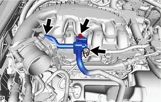
Disconnect the purge VSV connector.
-
Disconnect the No. 1 fuel vapor feed hose from the intake air surge tank assembly.
-
Remove the bolt to disconnect the purge VSV from the intake air surge tank assembly.
-
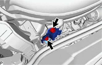
Disconnect the vacuum sensor connector.
-
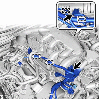
Detach the 3 clamps.
-
Remove the bolt to disconnect the wire harness.
-
Detach the clamp to disconnect the No. 1 fuel tube sub-assembly.
-
for RHD:
Detach the 2 clamps to disconnect the motor cable and generator cable.
-
Detach the 2 clamps to disconnect the transmission breather assembly.
-
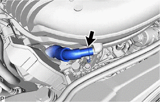
Slide the clamp and disconnect the PCV hose from the intake air surge tank assembly.
-
Remove the 2 bolts and No. 2 surge tank stay from the intake air surge tank assembly and camshaft housing sub-assembly LH.
-

Bolt 
Nut Remove the 2 nuts.
-
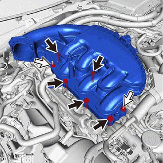
Remove the 5 bolts and intake air surge tank assembly.
-
Remove the air surge tank to intake manifold gasket from the intake air surge tank assembly.
-
-
REMOVE NO. 1 ENGINE COVER SUB-ASSEMBLY
-
REMOVE FUEL TUBE SUB-ASSEMBLY
-
DISCONNECT WIRE HARNESS
-
DISCONNECT FUEL DELIVERY PIPE SUB-ASSEMBLY
-
DISCONNECT GENERATOR CABLE AND MOTOR CABLE (for LHD)
-
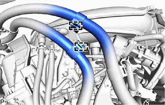
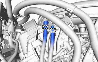
DISCONNECT NO. 15 WATER BY-PASS HOSE
-
REMOVE WATER BY-PASS HOSE
-
REMOVE EGR VALVE ASSEMBLY
-
REMOVE INTAKE MANIFOLD
-
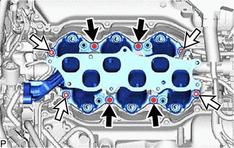
Bolt Nut Remove the 4 bolts, 4 nuts and intake manifold.
-
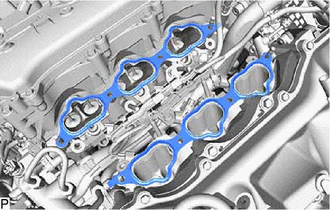
Remove the 2 No. 1 intake manifold to head gaskets.
-
-
REMOVE STUD BOLT
Tech Tips
If a stud bolt is deformed or the threads are damaged, replace it.
-
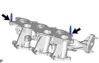
Using an E8 "TORX" socket wrench, remove the 2 stud bolts from the intake manifold.
-