EMISSION CONTROL SYSTEM ON-VEHICLE INSPECTION
CAUTION / NOTICE / HINT
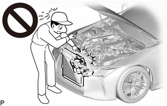
CAUTION:
To prevent injury due to contact with an operating V-ribbed belt or cooling fan, keep your hands and clothing away from the V-ribbed belt and cooling fans when working in the engine compartment with the engine running or the power switch on (IG).
PROCEDURE
-
VISUALLY CHECK HOSES, CONNECTIONS AND GASKETS
-
Visually check that the hoses, connections and gaskets have no cracks, leaks or damage.
Note
-
Detachment or other problems with the engine oil level dipstick, oil filler cap sub-assembly, PCV hose or other components may cause the engine to run improperly.
-
Air suction caused by disconnections, looseness or cracks in any part of the air induction system between the throttle body with motor assembly and cylinder head sub-assembly will cause engine failure or engine malfunctions.
If any defects are found, replace parts as necessary.
-
-
-
INSPECT EVAPORATIVE EMISSION CONTROL SYSTEM
CAUTION:
To prevent injury due to contact with an operating V-ribbed belt or cooling fan, keep your hands and clothing away from the V-ribbed belt and cooling fans when working in the engine compartment with the engine running or the power switch on (IG).
-
Connect the GTS to the DLC3.
-
Turn the power switch on (IG).
-
Turn the GTS on.
-
Put the engine in inspection mode (maintenance mode).
-
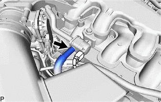
Disconnect the No. 2 fuel vapor feed hose from the purge VSV.
-
Enter the following menus: Powertrain / Engine / Active Test / Activate the Evap Purge VSV.
Powertrain > Engine > Active TestTester Display Activate the EVAP Purge VSV -
Check that vacuum occurs at the purge VSV port.
If vacuum does not occur, check the following items.
-
Purge VSV
-
Clogging in the No. 1 fuel vapor feed hose that connects the intake manifold and purge VSV
-
Voltage from the ECM PRG terminal
-
w/ Canister Pump Module:
-
w/o Canister Pump Module:
-
-
Exit Active Test mode and connect the No. 2 fuel vapor feed hose.
If the result is not as specified, replace the purge VSV, wire harness or ECM.
-
Enter the following menus: Powertrain / Engine / Data List / EVAP (Purge) VSV.
Powertrain > Engine > Data ListTester Display EVAP (Purge) VSV -
Warm up the engine and drive the vehicle.
-
Confirm that the purge VSV opens.
If the result is not as specified, replace the purge VSV, wire harness or ECM.
-
-
CHECK FUEL TANK AND VENT LINE (w/ Canister Pump Module)
-
Disconnect the fuel tank vent hose sub-assembly from the charcoal canister assembly.
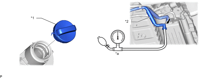
*1 Fuel Tank Cap Assembly *2 Fuel Tank Vent Hose Sub-assembly *a Pressure Gauge - - -
Connect a pressure gauge to the fuel tank vent hose sub-assembly.
-
Apply 4 kPa (0.04 kgf/cm2, 0.6 psi) of pressure to the vent line of the fuel tank assembly.
Tech Tips
Perform this inspection with the fuel tank assembly less than 90% full. When the fuel tank assembly is full, the fuel fill check valve closes and the pressure is released through the 2 mm (0.0787 in.) orifice. As a result, when the fuel tank cap assembly is removed, the pressure does not decrease smoothly.
-
Check that the fuel tank assembly pressure is maintained for some time and does not decrease immediately.
Tech Tips
If the pressure decreases immediately, one of the following may apply:
-
The fuel tank cap assembly is not completely tightened.
-
The fuel tank cap assembly is damaged.
-
Air is leaking from the vent line.
-
The fuel tank assembly is damaged.
-
-
Remove the fuel tank cap assembly and check that the pressure is released smoothly.
If the pressure is not released smoothly, replace the fuel tank assembly.
-
Connect the fuel tank vent hose sub-assembly to the charcoal canister assembly.
-
-
INSPECT AIR LINE (w/ Canister Pump Module)
-
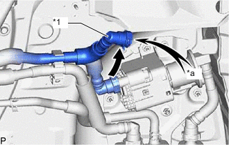
*1 Air Line Tube *a Air Disconnect the air line tube from the canister pump module.
-
Check that air flows freely into the air line.
If air does not flow freely into the air line, repair or replace the air line tube.
-
Connect the air line tube to the canister pump module.
-