FUEL SENDER GAUGE ASSEMBLY INSTALLATION
PROCEDURE
-
INSTALL FUEL SENDER GAUGE ASSEMBLY
-
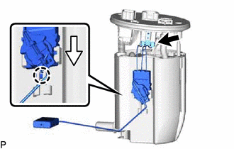
Set the fuel sender gauge assembly on the No. 1 fuel sub-tank. Then slide the fuel sender gauge assembly downward to install it.
-
Connect the fuel sender gauge assembly connector.
-
-
INSTALL FUEL SUCTION TUBE WITH PUMP AND GAUGE ASSEMBLY
-
INSTALL FUEL TANK VENT TUBE SET PLATE
-
CONNECT FUEL TANK MAIN TUBE SUB-ASSEMBLY
-
INSTALL NO. 2 REAR FLOOR SERVICE HOLE COVER
-
INSTALL NO. 2 FUEL SENDER GAUGE ASSEMBLY
-
Install the No. 2 fuel sender gauge assembly to the fuel tank assembly with the 5 screws.
- Torque:
- 1.5 N*m { 15 kgf*cm, 13 in.*lbf }
-
-
INSTALL NO. 1 REAR FLOOR SERVICE HOLE COVER
-
Connect the No. 2 fuel sender gauge assembly connector.
-
Install the No. 1 rear floor service hole cover with new butyl tape.
-
-
CONNECT CABLE TO NEGATIVE AUXILIARY BATTERY TERMINAL
Note
When disconnecting the cable, some systems need to be initialized after the cable is reconnected.
-
INSTALL NO. 2 DECK BOARD
-
INSPECT FOR FUEL LEAK
-
INSTALL REAR SEAT CUSHION ASSEMBLY