FUEL TANK(w/o Canister Pump Module) INSTALLATION

PROCEDURE
-
INSTALL NO. 1 FUEL TANK PROTECTOR SUB-ASSEMBLY
-
Install the No. 1 fuel tank protector sub-assembly to the fuel tank assembly.
-
-
INSTALL FUEL TUBE CLAMP BRACKET
-
Install the 2 fuel tube clamp brackets to the fuel tank assembly.
-
-
INSTALL FUEL TUBE GROMMET
-
Install the fuel tube grommet to the fuel tank assembly.
-
-
INSTALL NO. 4 FUEL TUBE CLAMP
-
Install the No. 4 fuel tube clamp to the fuel tank assembly.
-
-
INSTALL NO. 3 FUEL TUBE CLAMP
-
Install the No. 3 fuel tube clamp to the fuel tank assembly.
-
-
INSTALL FUEL TANK MAIN TUBE SUB-ASSEMBLY
-
Attach the 6 clamps and install the fuel tank main tube sub-assembly to the fuel tank assembly.
-
-
INSTALL NO. 1 FUEL TANK BREATHER TUBE SUB-ASSEMBLY
-
Install a new fuel tank breather tube gasket to the No. 1 fuel tank breather tube sub-assembly.
-
Install the No. 1 fuel tank breather tube sub-assembly to the fuel tank assembly with the 4 screws.
- Torque:
- 1.5 N*m { 15 kgf*cm, 13 in.*lbf }
-
-
INSTALL FUEL TANK TO CANISTER TUBE SUB-ASSEMBLY
-
Install the fuel tank to canister tube sub-assembly to the fuel tank assembly.
-
-
INSTALL FUEL TANK ASSEMBLY
-
Set the fuel tank assembly on an engine lifter with attachments.
-
Using an engine lifter, slowly raise the fuel tank assembly, and then install the fuel tank assembly.
Note
-
Slowly raise the fuel tank assembly while being careful not to drop it.
-
Do not allow the fuel tank assembly to contact the vehicle, especially the rear differential carrier assembly.
-
-
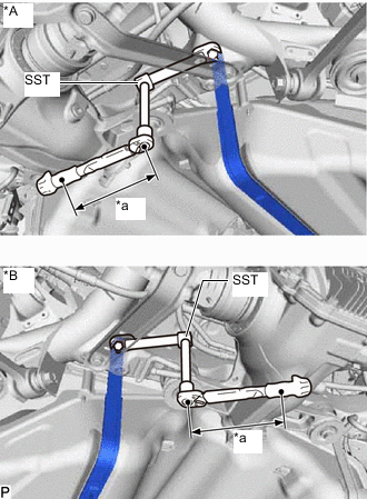
*A for RH Side *B for LH Side *a Torque Wrench Fulcrum Length Install the 2 fuel tank bands and 4 bolts.
- SST
- 09961-00950
Torque Specified tightening torque 45 N*m (459 kgf*cm, 33 ft.*lbf) Tech Tips
-
Using SST and a union nut wrench (14 mm), install the rear side of the fuel tank band.
-
Calculate the torque wrench reading when changing the fulcrum length of the torque wrench.
-
When using a union nut wrench (fulcrum length of 25 mm (0.984 in.)) + SST (fulcrum length of 150 mm (5.906 in.)) + torque wrench (fulcrum length of 180 mm (7.087 in.)): 22.8 N*m (232 kgf*cm, 17 ft.*lbf)
-
-
CONNECT FUEL TANK MAIN TUBE SUB-ASSEMBLY
-
Connect the 2 fuel tank main tube sub-assemblies.
-
-
CONNECT NO. 1 FUEL TANK BREATHER TUBE SUB-ASSEMBLY
-
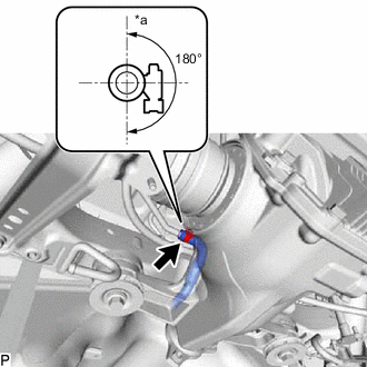
*a Top Connect the No. 1 fuel tank breather tube sub-assembly with the hose clamp.
Tech Tips
Make sure the hose clamp is oriented as shown in the illustration.
-
-
CONNECT FUEL TANK TO CANISTER TUBE SUB-ASSEMBLY
-
Connect the fuel tank to canister tube sub-assembly.
-
-
CONNECT FUEL TANK TO FILLER PIPE HOSE
-
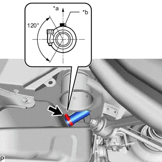
*a Top *b Paint Mark Connect the fuel tank to filler pipe hose with the hose clamp.
Tech Tips
Make sure the hose clamp is oriented as shown in the illustration.
-
-
INSTALL REAR LOWER SUSPENSION MEMBER STOPPER LH
-
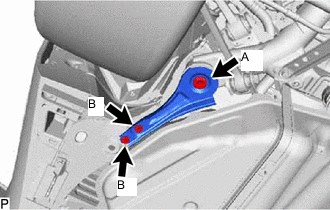
Install the rear lower suspension member stopper LH with the 3 bolts.
- Torque:
- for bolt A
- 135 N*m { 1377 kgf*cm, 100 ft.*lbf }
- for bolt B
- 19 N*m { 194 kgf*cm, 14 ft.*lbf }
-
-
INSTALL PROPELLER WITH CENTER BEARING SHAFT ASSEMBLY
-
ADD FUEL
-
INSTALL NO. 2 FUEL SENDER GAUGE ASSEMBLY
-
INSTALL FUEL SUCTION TUBE WITH PUMP AND GAUGE ASSEMBLY
-
CONNECT CABLE TO NEGATIVE AUXILIARY BATTERY TERMINAL
Note
When disconnecting the cable, some systems need to be initialized after the cable is reconnected.
-
INSTALL NO. 2 DECK BOARD