FUEL PUMP INSTALLATION
CAUTION / NOTICE / HINT
Tech Tips
Perform "Inspection After Repairs" after replacing the fuel suction tube with pump and gauge assembly.
-
w/ Canister Pump Module:
-
w/o Canister Pump Module:
PROCEDURE
-
INSTALL FUEL SUCTION TUBE WITH PUMP AND GAUGE ASSEMBLY
Tech Tips
Perform "Inspection After Repairs" after replacing the fuel suction tube with pump and gauge assembly.
-
w/ Canister Pump Module:
-
w/o Canister Pump Module:
-
Apply a light coat of gasoline to a new fuel suction tube set gasket, and install it to the fuel tank assembly.
-
Connect the fuel hose and set the fuel suction tube with pump and gauge assembly into the fuel tank assembly.
Note
-
Make sure that the fuel sender gauge assembly arm does not bend.
-
When connecting the fuel hose, do not forcibly pull the fuel hose.
-
-
-
INSTALL FUEL TANK VENT TUBE SET PLATE
-
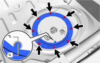
*a Protrusion *b Cutout w/ Canister Pump Module:
Install the fuel tank vent tube set plate and No. 2 fuel tank protector with the 8 bolts.
- Torque:
- 6.0 N*m { 61 kgf*cm, 53 in.*lbf }
Tech Tips
Align the protrusion of the fuel tank vent tube set plate with the cutout of the fuel suction tube with pump and gauge assembly.
-
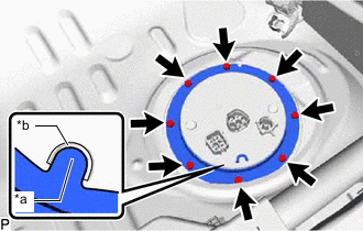
*a Protrusion *b Cutout w/o Canister Pump Module:
Install the fuel tank vent tube set plate with the 8 bolts.
- Torque:
- 6.0 N*m { 61 kgf*cm, 53 in.*lbf }
Tech Tips
Align the protrusion of the fuel tank vent tube set plate with the cutout of the fuel suction tube with pump and gauge assembly.
-
w/ Canister Pump Module:
Attach the 3 clamps and connect the fuel tank main tube sub-assembly and fuel tank wire to the No. 2 fuel tank protector.
-
-
CONNECT FUEL TANK MAIN TUBE SUB-ASSEMBLY
-
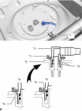
*1 Tube Joint Clip *2 Fuel Suction Plate Sub-assembly *a CORRECT *b INCORRECT *c Fuel Tube Joint *d O-Ring *e Collar Insert the fuel tank main tube sub-assembly into the plug of the fuel suction plate sub-assembly and fix them in place with the tube joint clip.
Note
-
Check that there are no scratches or foreign objects on the connecting parts.
-
Check that the fuel tube joint is inserted securely.
-
Check that the tube joint clips are on the collars of the fuel tube joints.
-
After installing the tube joint clips, check that the fuel tube joints have not been pulled off.
-
Be careful not to damage any tube joint clip. If a tube joint clip is damaged, replace it.
-
-
-
INSTALL NO. 2 REAR FLOOR SERVICE HOLE COVER
-
w/ Canister Pump Module:
Connect the fuel pump connector, fuel sender gauge assembly connector and fuel tank pressure sensor connector.
-
w/o Canister Pump Module:
Connect the fuel pump connector and fuel sender gauge assembly connector.
-
Install the No. 2 rear floor service hole cover with new butyl tape.
-
-
CONNECT CABLE TO NEGATIVE AUXILIARY BATTERY TERMINAL
Note
When disconnecting the cable, some systems need to be initialized after the cable is reconnected.
-
INSTALL NO. 2 DECK BOARD
-
INSPECT FOR FUEL LEAK
-
INSTALL REAR SEAT CUSHION ASSEMBLY