FUEL PUMP REMOVAL
CAUTION / NOTICE / HINT
The necessary procedures (adjustment, calibration, initialization or registration) that must be performed after parts are removed and installed, or replaced during fuel pump removal/installation are shown below.
| Replaced Part or Performed Procedure | Necessary Procedure | Effect/Inoperative Function when Necessary Procedure not Performed | Link |
|---|---|---|---|
| Auxiliary battery terminal is disconnected/reconnected | Memorize steering angle neutral point | LKA/LDA system | |
| Pre-collision system | |||
| Parking assist monitor system | |||
| Steering sensor zero point calibration | Variable gear ratio steering system | ||
| Replacement of fuel pump | Inspection After Repair |
|
|
CAUTION:
-
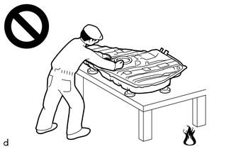
Never perform work on fuel system components near any possible ignition sources.
-
Vaporized fuel could ignite, resulting in a serious accident.
-
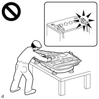
Do not perform work on fuel system components without first disconnecting the cable from the negative (-) battery terminal.
-
Sparks could cause vaporized fuel to ignite, resulting in a serious accident.
PROCEDURE
-
REMOVE NO. 2 DECK BOARD
-
DISCHARGE FUEL SYSTEM PRESSURE
-
PRECAUTION
Note
After turning the power switch off, waiting time may be required before disconnecting the cable from the auxiliary battery terminal. Therefore, make sure to read the disconnecting the cable from the auxiliary battery terminal notice before proceeding with work.
-
DISCONNECT CABLE FROM NEGATIVE AUXILIARY BATTERY TERMINAL
Note
When disconnecting the cable, some systems need to be initialized after the cable is reconnected.
-
REMOVE REAR SEAT CUSHION ASSEMBLY
-
REMOVE NO. 2 REAR FLOOR SERVICE HOLE COVER
-
w/ Canister Pump Module:
-
Remove the No. 2 rear floor service hole cover.
-
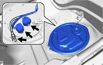
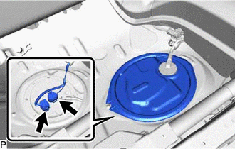
Disconnect the fuel pump connector, fuel sender gauge assembly connector and fuel tank pressure sensor connector.
-
-
w/o Canister Pump Module:
-
Remove the No. 2 rear floor service hole cover.
-
Disconnect the fuel pump connector and fuel sender gauge assembly connector.
-
-
-
DISCONNECT FUEL TANK MAIN TUBE SUB-ASSEMBLY
-
w/ Canister Pump Module:
Disconnect the fuel tank main tube sub-assembly.
-
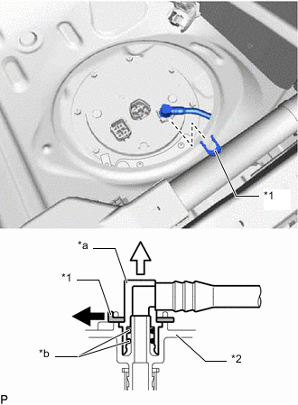
*1 Tube Joint Clip *2 Fuel Suction Plate Sub-assembly *a Fuel Tube Joint *b O-Ring Remove the tube joint clip and disconnect the fuel tank main tube sub-assembly.
Note
-
Remove any dirt and foreign matter on the fuel tube joint before performing this step.
-
Do not allow any scratches or foreign matter on the parts when disconnecting them as the fuel tube joint contains the O-rings that seal the plug.
-
Perform this step by hand. Do not use any tools.
-
Do not forcibly bend, twist or turn the nylon tube.
-
Protect the disconnected part by covering it with a plastic bag and tape after disconnecting the fuel tank main tube sub-assembly.
-
-
-
w/o Canister Pump Module:
Disconnect the fuel tank main tube sub-assembly.
-
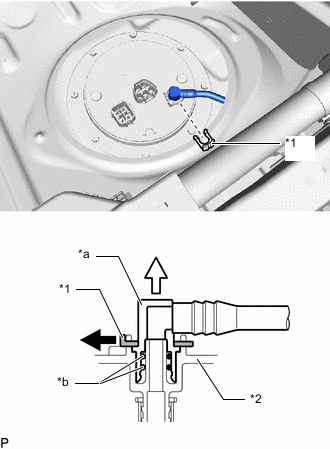
*1 Tube Joint Clip *2 Fuel Suction Plate Sub-assembly *a Fuel Tube Joint *b O-Ring Remove the tube joint clip and disconnect the fuel tank main tube sub-assembly.
Note
-
Remove any dirt and foreign matter on the fuel tube joint before performing this step.
-
Do not allow any scratches or foreign matter on the parts when disconnecting them as the fuel tube joint contains the O-rings that seal the plug.
-
Perform this step by hand. Do not use any tools.
-
Do not forcibly bend, twist or turn the nylon tube.
-
Protect the disconnected part by covering it with a plastic bag and tape after disconnecting the fuel tank main tube sub-assembly.
-
-
-
-
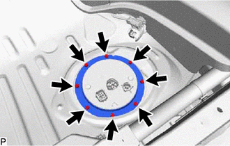
REMOVE FUEL TANK VENT TUBE SET PLATE
-
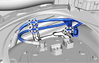
w/ Canister Pump Module:
Detach the 3 clamps and disconnect the fuel tank main tube sub-assembly and fuel tank wire from the No. 2 fuel tank protector.
-
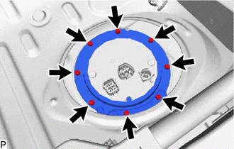
w/ Canister Pump Module:
Remove the 8 bolts, No. 2 fuel tank protector and fuel tank vent tube set plate.
-
w/o Canister Pump Module:
Remove the 8 bolts and fuel tank vent tube set plate.
-
-
REMOVE FUEL SUCTION TUBE WITH PUMP AND GAUGE ASSEMBLY
-
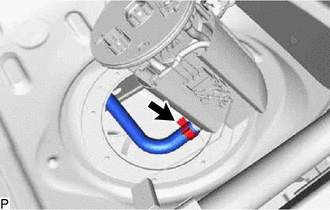
Slide the clamp and disconnect the fuel hose from the fuel suction tube with pump and gauge assembly.
Note
-
Make sure that the fuel sender gauge assembly arm does not bend.
-
When disconnecting the fuel hose, do not forcibly pull the fuel hose.
-
-
Remove the fuel suction tube with pump and gauge assembly from the fuel tank assembly.
-
Remove the fuel suction tube set gasket from the fuel suction tube with pump and gauge assembly.
-