HV BATTERY STACK INSTALLATION
PROCEDURE
-
INSTALL NO. 9 HYBRID BATTERY INTAKE DUCT
CAUTION:
Be sure to wear insulated gloves and protective goggles.
-
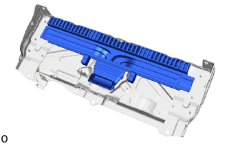
Install the No. 9 hybrid battery intake duct.
-
-
INSTALL NO. 2 HV SUPPLY STACK SUB-ASSEMBLY
CAUTION:
Be sure to wear insulated gloves and protective goggles.
-
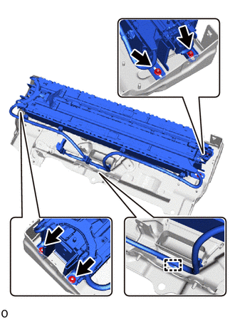
Install the HV supply stack sub-assembly No. 2 with the 4 nuts.
- Torque:
- 7.5 N*m { 76 kgf*cm, 66 in.*lbf }
-
Attach the clamp.
-
-
INSTALL NO. 2 HV BATTERY PACK WIRE
CAUTION:
Be sure to wear insulated gloves and protective goggles.
-
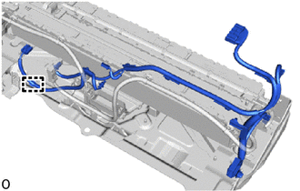
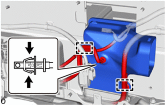
Attach the clamp and install the No. 2 HV battery pack wire.
-
-
INSTALL NO. 7 HV BATTERY SHIELD SUB-ASSEMBLY (for Lower Side)
CAUTION:
Be sure to wear insulated gloves and protective goggles.
-
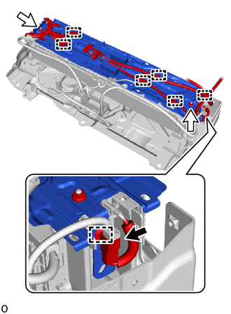
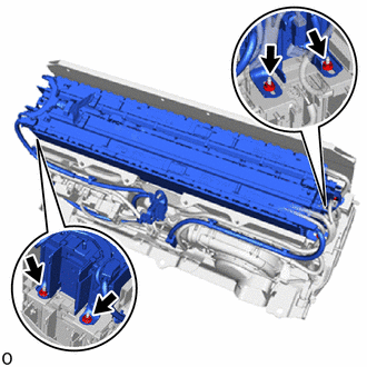
Install the No. 7 HV battery shield sub-assembly and wire harness clamp bracket with the 2 nuts.
- Torque:
- 7.5 N*m { 76 kgf*cm, 66 in.*lbf }
-
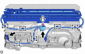
Attach the 7 clamps.
-
Connect the connector.
Note
Make sure that the connector is connected securely.
-
-
INSTALL BATTERY VOLTAGE SENSOR (for Lower Side)
-
INSTALL UPPER HV BATTERY CARRIER SUB-ASSEMBLY
CAUTION:
Be sure to wear insulated gloves and protective goggles.
-
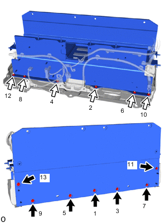
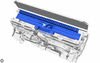
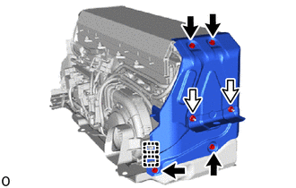
Install the upper HV battery carrier sub-assembly.
-
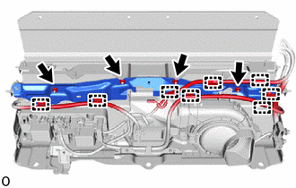
While pressing the upper HV battery carrier sub-assembly downwards, tighten the 7 bolts and 6 nuts in the order shown in the illustration.
- Torque:
- 7.5 N*m { 76 kgf*cm, 66 in.*lbf }
Note
After installing, check that the upper HV battery carrier sub-assembly is properly installed.
Tech Tips
-
An elastic body for resonance countermeasures with the No. 2 HV supply stack sub-assembly exists in the center of the No. 7 HV battery shield sub-assembly and generates a reactive force by being squashed by the upper HV battery carrier sub-assembly.
-
Install the upper HV battery carrier sub-assembly while pressing downwards with 475 to 517 N (48 to 53 kgf, 106.8 to 116.2 lbf).
-
-
INSTALL HV BATTERY JUNCTION BLOCK ASSEMBLY
CAUTION:
Be sure to wear insulated gloves and protective goggles.
-
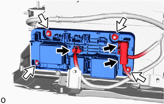
Install the HV battery junction block assembly with the 4 nuts.
- Torque:
- 7.5 N*m { 76 kgf*cm, 66 in.*lbf }
Note
-
Do not drop the HV battery junction block assembly, strike it with tools or subject it to impact.
-
If the HV battery junction block assembly is subjected to an impact, replace it with a new one.
-
Connect the 3 connectors.
Note
Make sure that the connector is connected securely.
-
-
INSTALL NO. 6 HYBRID BATTERY INTAKE DUCT
CAUTION:
Be sure to wear insulated gloves and protective goggles.
-
Install the No. 6 hybrid battery intake duct.
-
Connect the HV battery intake air temperature sensor.
-
Attach the 2 clamps.
-
-
INSTALL BATTERY COOLING BLOWER ASSEMBLY
CAUTION:
Be sure to wear insulated gloves and protective goggles.
-
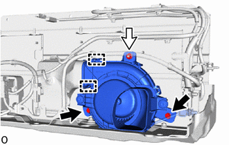
Connect the 2 fittings on the No. 6 hybrid battery intake duct and install the battery cooling blower assembly.
-
Install the 2 bolts and nut.
- Torque:
- 7.5 N*m { 76 kgf*cm, 66 in.*lbf }
-
-
INSTALL WIRE HARNESS CLAMP BRACKET
CAUTION:
Be sure to wear insulated gloves and protective goggles.
-
Install the wire harness clamp bracket with the 4 nuts.
- Torque:
- 7.5 N*m { 76 kgf*cm, 66 in.*lbf }
-
Attach the 8 clamps.
-
-
INSTALL NO. 8 HYBRID BATTERY INTAKE DUCT
CAUTION:
Be sure to wear insulated gloves and protective goggles.
-
Install the No. 8 hybrid battery intake duct.
-
-
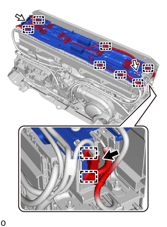
INSTALL NO. 1 HV SUPPLY STACK SUB-ASSEMBLY
CAUTION:
Be sure to wear insulated gloves and protective goggles.
-
Install the No. 1 HV supply stack sub-assembly with the 4 nuts.
- Torque:
- 7.5 N*m { 76 kgf*cm, 66 in.*lbf }
-
Install the nut.
- Torque:
- 7.5 N*m { 76 kgf*cm, 66 in.*lbf }
-
Attach the 6 clamps.
-
Connect the 2 connectors.
Note
Make sure that the connector is connected securely.
-
-
INSTALL NO. 7 HV BATTERY SHIELD SUB-ASSEMBLY (for Upper Side)
CAUTION:
Be sure to wear insulated gloves and protective goggles.
-
Install the No. 7 HV battery shield sub-assembly and wire harness clamp bracket with the 2 nuts.
- Torque:
- 7.5 N*m { 76 kgf*cm, 66 in.*lbf }
-
Attach the 9 clamps.
-
Connect the connector.
Note
Make sure that the connector is connected securely.
-
-
INSTALL BATTERY ECU ASSEMBLY
-
INSTALL BATTERY VOLTAGE SENSOR (for Upper Side)
-
INSTALL NO. 1 HYBRID BATTERY EXHAUST DUCT
CAUTION:
Be sure to wear insulated gloves and protective goggles.
-
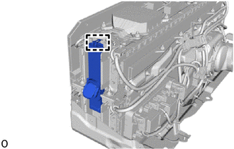
Attach the guide and install the No. 1 hybrid battery exhaust duct.
-
-
INSTALL UPPER NO. 1 HYBRID BATTERY COVER SUB-ASSEMBLY
CAUTION:
Be sure to wear insulated gloves and protective goggles.
-
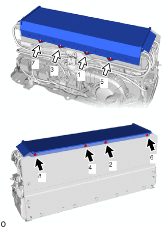
Install the upper No. 1 hybrid battery cover sub-assembly.
-
While pressing the upper No. 1 hybrid battery cover sub-assembly downwards, tighten the 4 bolts and 4 nuts in the order shown in the illustration.
- Torque:
- 7.5 N*m { 76 kgf*cm, 66 in.*lbf }
Note
After installing, check that the upper No. 1 hybrid battery cover sub-assembly is properly installed.
Tech Tips
-
An elastic body for resonance countermeasures with the No. 1 HV supply stack sub-assembly exists in the center of the No. 7 HV battery shield sub-assembly and generates a reactive force by being squashed by the upper No. 1 hybrid battery cover sub-assembly.
-
Install the upper No. 1 hybrid battery cover sub-assembly while pressing downwards with 426 N (43 kgf, 95.8 lbf) or more.
-
-
INSTALL HYBRID BATTERY TERMINAL BLOCK
-
INSTALL NO. 1 HYBRID BATTERY SHIELD SUB-ASSEMBLY
CAUTION:
Be sure to wear insulated gloves and protective goggles.
-
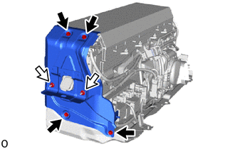
Install the No. 1 hybrid battery shield sub-assembly with the 4 bolts and 2 nuts.
- Torque:
- 7.5 N*m { 76 kgf*cm, 66 in.*lbf }
-
-
INSTALL NO. 2 HYBRID BATTERY SHIELD SUB-ASSEMBLY
CAUTION:
Be sure to wear insulated gloves and protective goggles.
-
Install the No. 2 hybrid battery shield sub-assembly with the 4 bolts and 2 nuts.
- Torque:
- 7.5 N*m { 76 kgf*cm, 66 in.*lbf }
-
Attach the 2 clamps.
-
-
INSTALL UPPER HV BATTERY COVER PANEL
CAUTION:
Be sure to wear insulated gloves and protective goggles.
-
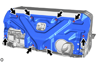
Install the upper HV battery cover panel with the 8 nuts.
- Torque:
- 7.5 N*m { 76 kgf*cm, 66 in.*lbf }
-
-
INSTALL HV BATTERY ASSEMBLY
-
PERFORM UTILITY
Note
-
Perform "Battery Status Info Update" after replacing a malfunctioning HV supply stack sub-assembly.
-
Perform "Prediagnostic Battery Charge" after replacing a malfunctioning HV supply stack sub-assembly.
-
Perform "Battery Diagnosis" after replacing a malfunctioning HV supply stack sub-assembly.
-