CYLINDER HEAD GASKET REMOVAL
CAUTION / NOTICE / HINT
The necessary procedures (adjustment, calibration, initialization, or registration) that must be performed after parts are removed, installed, or replaced during the cylinder head gasket removal/installation are shown below.
| Replaced Part or Performed Procedure | Necessary Procedure | Effect/Inoperative Function when Necessary Procedure not Performed | Link |
|---|---|---|---|
| Auxiliary battery terminal is disconnected/reconnected | Memorize steering angle neutral point | LKA/LDA system | |
| Pre-collision system | |||
| Parking assist monitor system | |||
| Steering sensor zero point calibration | Variable gear ratio steering system | ||
| Replacement of ECM | Vehicle Identification Number (VIN) registration | DTC P063051 is output | w/ Canister Pump Module: Click here w/o Canister Pump Module: Click here |
|
Inspection after repair |
|
w/ Canister Pump Module: Click here w/o Canister Pump Module: Click here |
| Replacement of engine assembly | Inspection after repair | ||
| Drive learning*2 |
|
||
| Parts between the steering wheel and tires have been removed/installed, replaced or adjusted | Perform Actuator Angle Neutral Point Calibration and Initialization |
|
|
| Suspension, tires, etc*1 | Television camera assembly optical axis (Back camera position setting) | Parking assist monitor system |
*2: After performing the confirmation driving pattern, if the shock during acceleration is large after calibrating the "A/T Code Reset", perform driving learning.
PROCEDURE
-
REMOVE TIMING CHAIN COVER ASSEMBLY
-
SET NO. 1 CYLINDER TO TDC/COMPRESSION
-
REMOVE NO. 1 CHAIN TENSIONER ASSEMBLY
-
REMOVE CHAIN TENSIONER SLIPPER
-
REMOVE CHAIN SUB-ASSEMBLY
-
REMOVE CAMSHAFT TIMING GEARS AND NO. 2 CHAIN SUB-ASSEMBLY (for Bank 1)
-
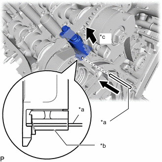
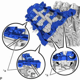
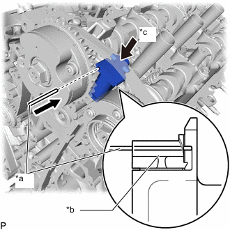
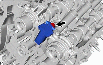
*a Pin *b Plunger *c Push While raising the No. 2 chain tensioner assembly, insert a pin of 1.0 mm (0.0394 in.) diameter into the hole to hold the No. 2 chain tensioner assembly.
-
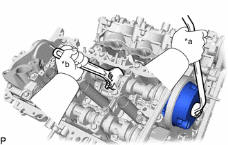
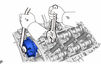
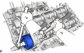
*a Turn *b Hold Using a wrench to hold the hexagonal portion of each camshaft, loosen the camshaft timing gear bolt of the camshaft timing gear assembly.
Note
-
Be careful not to damage the cylinder head sub-assembly with the wrench.
-
Do not loosen the other bolts. If any of the bolts is loosened, replace the camshaft timing gear assembly and/or the camshaft timing exhaust gear assembly with a new one.
-
-
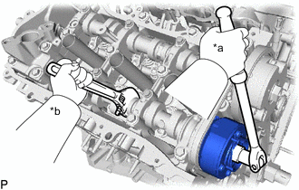
*a Turn *b Hold Using a wrench to hold the hexagonal portion of each camshaft, loosen the camshaft timing gear bolt of the camshaft timing exhaust gear assembly RH.
Note
-
Be careful not to damage the cylinder head sub-assembly with the wrench.
-
Do not loosen the other bolts. If any of the bolts is loosened, replace the camshaft timing gear assembly and/or the camshaft timing exhaust gear assembly with a new one.
-
-
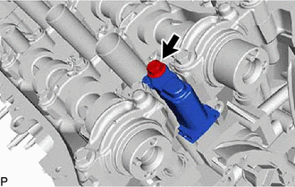
Remove the 2 bolts and the camshaft timing gear assembly together with the No. 2 chain.
-
-
REMOVE NO. 2 CHAIN TENSIONER ASSEMBLY
-
Remove the bolt and No. 2 chain tensioner assembly.
-
-
REMOVE CAMSHAFT BEARING CAP (for Bank 1)
-
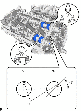
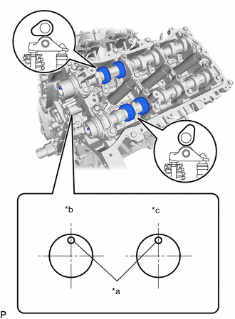
*a Knock Pin *b IN *c EX Check that the camshafts are positioned as shown in the illustration.
-
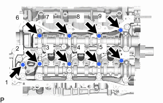
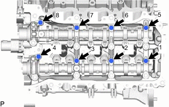
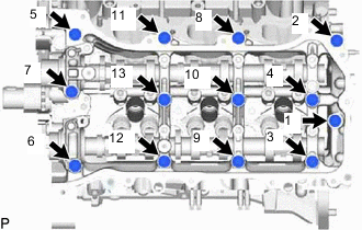
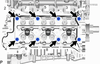
Uniformly loosen and remove the 9 bearing cap bolts in several steps and in the sequence shown in the illustration.
-
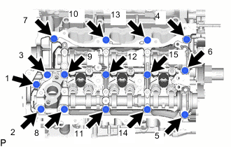
Uniformly loosen and remove the 15 bearing cap bolts in several steps and in the sequence shown in the illustration.
Note
Uniformly loosen the bolts while keeping the camshaft level.
-
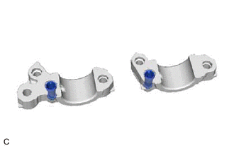
Remove the 2 oil control valve filters from the 2 camshaft bearing caps.
-
-
REMOVE FUEL PUMP LIFTER HOUSING
-
Remove the fuel pump lifter housing.
-
-
REMOVE CAMSHAFT
-
Remove the camshaft from the camshaft housing sub-assembly.
-
-
REMOVE NO. 2 CAMSHAFT
-
Remove the No. 2 camshaft from the camshaft housing sub-assembly.
-
-
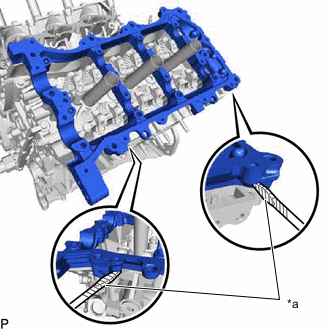
REMOVE CAMSHAFT HOUSING SUB-ASSEMBLY RH
-
*a Protective Tape Remove the camshaft housing RH by prying between the cylinder head sub-assembly and camshaft housing RH with a screwdriver.
Note
Be careful not to damage the contact surfaces of the cylinder head sub-assembly and camshaft housing RH.
Tech Tips
Tape the screwdriver tip before use.
-
-
REMOVE CAMSHAFT TIMING GEARS AND NO. 2 CHAIN (for Bank 2)
-
*a Pin *b Plunger *c Push While pushing down the No. 3 chain tensioner assembly, insert a pin of 1.0 mm (0.0394 in.) diameter into the hole to hold the No. 3 chain tensioner assembly.
-
*a Turn *b Hold Using a wrench to hold the hexagonal portion of each camshaft, loosen the camshaft timing gear bolt of the camshaft timing gear assembly.
Note
-
Be careful not to damage the cylinder head sub-assembly with the wrench.
-
Do not loosen the other bolts. If any of the bolts is loosened, replace the camshaft timing gear assembly and/or the camshaft timing exhaust gear assembly with a new one.
-
-
*a Turn *b Hold Using a wrench to hold the hexagonal portion of each camshaft, loosen the camshaft timing gear bolt of the camshaft timing exhaust gear assembly LH.
Note
-
Be careful not to damage the cylinder head sub-assembly with the wrench.
-
Do not loosen the other bolts. If any of the bolts is loosened, replace the camshaft timing gear assembly and/or the camshaft timing exhaust gear assembly with a new one.
-
-
Remove the 2 bolts and the camshaft timing gear together with the No. 2 chain sub-assembly.
-
-
REMOVE NO. 3 CHAIN TENSIONER ASSEMBLY
-
Remove the bolt and No. 3 chain tensioner assembly.
-
-
REMOVE CAMSHAFT BEARING CAP (for Bank 2)
-
*a Knock Pin *b IN *c EX Check that the camshafts are positioned as shown in the illustration.
-
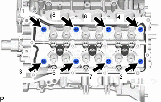
Uniformly loosen and remove the 8 bearing cap bolts in several steps and in the sequence shown in the illustration.
-
Uniformly loosen and remove the 13 bearing cap bolts in several steps and in the sequence shown in the illustration.
Note
Uniformly loosen the bolts while keeping the camshaft level.
-
Remove the 5 camshaft bearing caps.
-
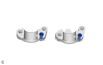
Remove the 2 oil control valve filters from the 2 camshaft bearing caps.
-
-
REMOVE NO. 3 CAMSHAFT SUB-ASSEMBLY
-
Remove the No. 3 camshaft sub-assembly from the camshaft housing sub-assembly LH.
-
-
REMOVE NO. 4 CAMSHAFT SUB-ASSEMBLY
-
Remove the No. 4 camshaft sub-assembly from the camshaft housing sub-assembly LH.
-
-
REMOVE CAMSHAFT HOUSING SUB-ASSEMBLY LH
-
*a Protective Tape Remove the camshaft housing LH by prying between the cylinder head LH and camshaft housing LH with a screwdriver.
Note
Be careful not to damage the contact surfaces of the cylinder head and camshaft housing LH.
Tech Tips
Tape the screwdriver tip before use.
-
-
REMOVE NO. 1 CHAIN VIBRATION DAMPER
-
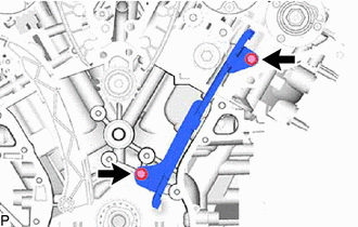
Remove the 2 bolts and No. 1 chain vibration damper.
-
-
REMOVE NO. 2 CHAIN VIBRATION DAMPER
-
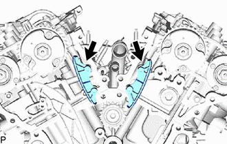
Remove the 2 No. 2 chain vibration dampers.
-
-
REMOVE NO. 1 VALVE ROCKER ARM SUB-ASSEMBLY
-
Remove the 24 No. 1 valve rocker arm sub-assemblies.
Tech Tips
Arrange the removed parts in the correct order.
-
-
REMOVE VALVE LASH ADJUSTER ASSEMBLY
-
Remove the 24 valve lash adjuster sub-assemblies from the cylinder head sub-assembly.
Tech Tips
Arrange the removed parts in the correct order.
-
-
REMOVE VALVE STEM CAP
-
Remove the 24 valve stem caps.
Tech Tips
Arrange the removed parts in the correct order.
-
-
REMOVE REAR WATER BY-PASS JOINT
-
REMOVE NO. 2 FUEL PIPE SUB-ASSEMBLY
-
REMOVE FUEL DELIVERY WITH SENSOR PIPE ASSEMBLY LH
-
REMOVE FUEL DELIVERY PIPE RH
-
REMOVE FUEL INJECTOR ASSEMBLY (for Direct Injection)
-
REMOVE FUEL INJECTOR SEAL
-
REMOVE CYLINDER HEAD SUB-ASSEMBLY
-
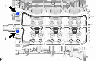
Using a 10 mm bi-hexagon wrench, uniformly loosen the 8 bolts in the sequence shown in the illustration. Remove the 8 cylinder head set bolts and plate washers.
Note
-
Be careful not to drop washers into the cylinder head sub-assembly.
-
Cylinder head warpage or cracking could result from removing bolts in an incorrect order.
Tech Tips
Be sure to keep separate the removed parts for each installation position.
-
-
Remove the cylinder head sub-assembly.
-
-
REMOVE CYLINDER HEAD GASKET
-
Remove the cylinder head gasket from the cylinder block sub-assembly.
-
-
REMOVE CYLINDER HEAD LH
-
Uniformly loosen and remove the bolts in the sequence shown in the illustration.
-
Using a 10 mm bi-hexagon wrench, uniformly loosen the 8 bolts in the sequence shown in the illustration. Remove the 8 cylinder head set bolts and plate washers.
Note
-
Be careful not to drop washers into the cylinder head.
-
Cylinder head warpage or cracking could result from removing bolts in an incorrect order.
Tech Tips
Be sure to keep separate the removed parts for each installation position.
-
-
Remove the cylinder head LH.
-
-
REMOVE NO. 2 CYLINDER HEAD GASKET
-
Remove the No. 2 cylinder head gasket from the cylinder block sub-assembly.
-
-
INSPECT CYLINDER HEAD SET BOLT
-
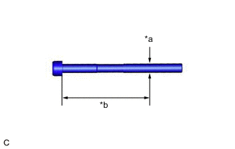
*a Measurement Point *b 100 mm Using a vernier caliper, measure the diameter of the threads at the measurement point.
Standard Diameter 10.85 to 11.00 mm (0.427 to 0.433 in.) Minimum Diameter 10.70 mm (0.421 in.) Measurement Point (Distance from the Seat) 100 mm (3.94 in.) Tech Tips
-
If the diameter is less than the minimum, replace the cylinder head set bolt. Failure to do so may lead to engine damage.
-
If there is any thread deformation, replace the cylinder head set bolt with a new one.
-
-
-
INSPECT CYLINDER HEAD SUB-ASSEMBLY