WATER PUMP WITH MOTOR INSTALLATION

PROCEDURE
-
INSTALL INVERTER WATER PUMP ASSEMBLY (WITH MOTOR)
-
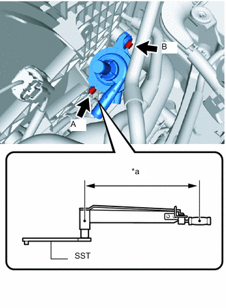
*a Torque Wrench Fulcrum Length Temporarily install the inverter water pump assembly (with motor) with the 2 nuts.
-
Temporarily install the bolt A.
-
Tighten the bolt B.
- Torque:
- 7.0 N*m { 71 kgf*cm, 62 in.*lbf }
Note
The fan shroud may be damaged by overtightening the bolt. Therefore, be sure to use a torque wrench for tightening.
-
Using SST, tighten the bolt A.
- SST
- 09961-00950
Note
The fan shroud may be damaged by overtightening the bolt. Therefore, be sure to use a torque wrench for tightening.
- Torque:
- Specified tightening torque
- 7.0 N*m { 71 kgf*cm, 62 in.*lbf }
Tech Tips
-
Calculate the torque wrench reading when changing the fulcrum length of the torque wrench.
-
When using SST (fulcrum length of 150 mm (5.906 in.)) + torque wrench (fulcrum length of 185 mm (7.283 in.)): 3.9 N*m (40 kgf*cm, 35 in.*lbf)
-
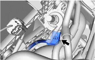
Connect the connector.
Note
-
If the connector of the inverter water pump assembly (with motor) is equipped with a dust prevention cap, remove the cap just before connecting the connector.
-
Make sure that the connector is connected securely.
-
-
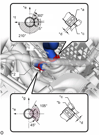
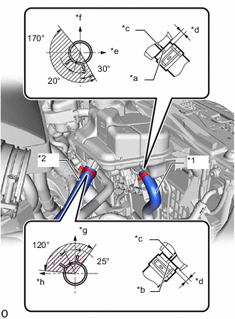
*1 No. 1 Inverter Cooling Hose *2 No. 2 Inverter Cooling Hose *a Alignment Mark (White) *b Alignment Mark (Green) *c Rib *d 2.0 to 5.0 mm (0.079 to 0.196 in.) *e Front of Vehicle *f LH Side *g Upper Side Connect the No. 1 inverter cooling hose and No. 2 inverter cooling hose to the inverter water pump assembly (with motor) and slide the 2 hose clips to secure them.
Note
To prevent foreign matter from entering the inverter water pump assembly (with motor) and inverter cooling system, do not remove the pieces of cloth from the pipes and disconnected hoses until installation.
Tech Tips
-
Make sure to align the alignment marks of the hoses with the ribs of the inverter water pump assembly (with motor).
-
Make sure that the clips are positioned as shown in the illustration.
-
-
-
INSTALL INVERTER RESERVE TANK ASSEMBLY
-
for LHD:
-
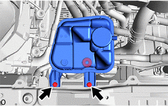
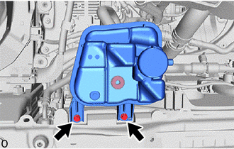
Connect the grommet and install the inverter reserve tank assembly.
-
Install the 2 bolts.
- Torque:
- 5.0 N*m { 51 kgf*cm, 44 in.*lbf }
Note
The fan shroud may be damaged by overtightening the bolt. Therefore, be sure to use a torque wrench for tightening.
-
*1 No. 1 Inverter Cooling Hose *2 No. 6 Inverter Cooling Hose *a Alignment Mark (Green) *b Alignment Mark (Pink) *c Rib *d 2.0 to 5.0 mm (0.079 to 0.196 in.) *e Front of Vehicle *f RH Side *g Upper Side *h LH Side Connect the No. 1 inverter cooling hose and No. 6 inverter cooling hose to the inverter reserve tank assembly and slide the 2 hose clips to secure them.
Note
To prevent foreign matter from entering the inverter reserve tank assembly and inverter cooling system, do not remove the pieces of cloth from the pipes and disconnected hoses until installation.
Tech Tips
-
Make sure to align the alignment marks of the hoses with the ribs of the inverter reserve tank assembly.
-
Make sure that the clips are positioned as shown in the illustration.
-
-
-
for RHD:
-
Connect the grommet and install the inverter reserve tank assembly.
-
Install the 2 bolts.
- Torque:
- 5.0 N*m { 51 kgf*cm, 44 in.*lbf }
Note
The fan shroud may be damaged by overtightening the bolt. Therefore, be sure to use a torque wrench for tightening.
-
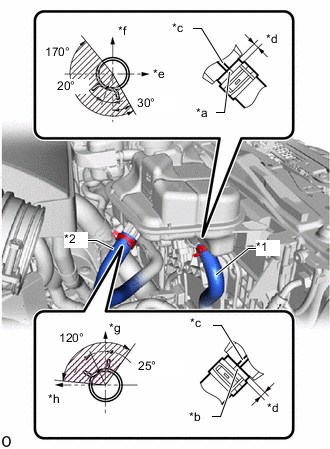
*1 No. 1 Inverter Cooling Hose *2 No. 2 Inverter Cooling Hose Assembly *a Alignment Mark (Green) *b Alignment Mark (Pink) *c Rib *d 2.0 to 5.0 mm (0.079 to 0.196 in.) *e Front of Vehicle *f RH Side *g Upper Side *h LH Side Connect the No. 1 inverter cooling hose and No. 2 inverter cooling hose assembly to the inverter reserve tank assembly and slide the 2 hose clips to secure them.
Note
To prevent foreign matter from entering the inverter reserve tank assembly and inverter cooling system, do not remove the pieces of cloth from the pipes and disconnected hoses until installation.
Tech Tips
-
Make sure to align the alignment marks of the hoses with the ribs of the inverter reserve tank assembly.
-
Make sure that the clips are positioned as shown in the illustration.
-
-
-
-
INSTALL AIR CLEANER ASSEMBLY
-
INSTALL NO. 1 AIR CLEANER INLET
-
INSTALL RADIATOR SUPPORT TO CROSSMEMBER BRACE SUB-ASSEMBLY RH
-
INSTALL LOWER RADIATOR AIR DEFLECTOR
-
INSTALL RADIATOR SUPPORT TO FRAME SEAL RH
-
ADD COOLANT (for Inverter)
-
INSPECT FOR COOLANT LEAK (for Inverter)
-
BLEED COOLANT (for Inverter)