HV BATTERY INSTALLATION

PROCEDURE
-
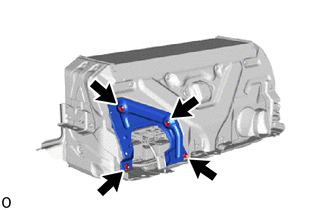
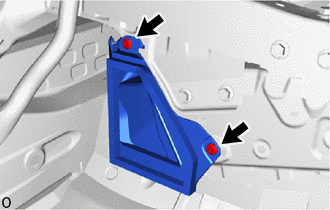
INSTALL HV BATTERY BRACKET LH
CAUTION:
Wear insulated gloves.
-
Install the HV battery bracket LH with the bolt and 2 nuts.
- Torque:
- 7.5 N*m { 76 kgf*cm, 66 in.*lbf }
-
-
INSTALL HV BATTERY BRACKET RH
Tech Tips
Use the same procedure described for the HV battery bracket LH.
-
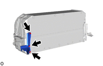
INSTALL NO. 9 HV BATTERY SHIELD PANEL
CAUTION:
Wear insulated gloves.
-
Install the No. 9 HV battery shield panel with the 4 nuts.
- Torque:
- 7.5 N*m { 76 kgf*cm, 66 in.*lbf }
-
-
INSTALL HV BATTERY DUCT SUB-ASSEMBLY
CAUTION:
Wear insulated gloves.
-
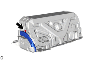
Install the HV battery duct sub-assembly with the clip.
-
-
INSTALL HV BATTERY ASSEMBLY
CAUTION:
Wear insulated gloves.
-
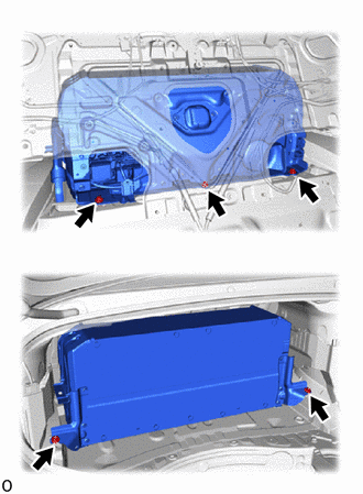
Install the HV battery assembly with the 3 bolts and 2 nuts.
- Torque:
- 20 N*m { 204 kgf*cm, 15 ft.*lbf }
Note
-
Do not allow foreign matter, such as grease or oil, to adhere to the bolts of the HV battery.
-
To prevent the wire harness from being caught, make sure to bundle the wire harness using insulating tape or equivalent.
-
Use cardboard or another similar material to protect the HV battery and vehicle body from damage.
-
Since the HV battery is very heavy, 2 people are needed to remove it. When removing the HV battery, be careful not to damage the parts around it.
-
When removing/installing/moving the HV battery, make sure not to tilt it more than 80°.
-
If the HV battery has been struck or dropped, replace it.
-
-
INSTALL NO. 4 HV BATTERY EXHAUST DUCT
CAUTION:
Wear insulated gloves.
-
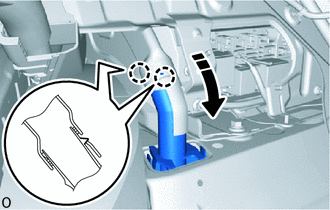
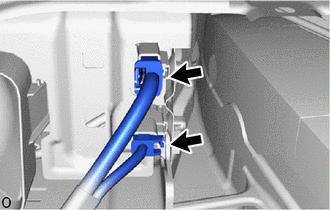
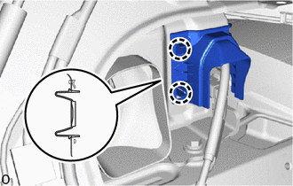
Install the No. 4 HV battery exhaust duct.
-
Attach the 2 claws as shown in the illustration.
-
-
CONNECT HV FLOOR UNDER WIRE
CAUTION:
Wear insulated gloves.
-
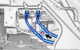
Connect the 2 connectors and install the nut.
- Torque:
- 8.0 N*m { 82 kgf*cm, 71 in.*lbf }
-
-
INSTALL NO. 10 HV BATTERY SHIELD PANEL
CAUTION:
Wear insulated gloves.
-
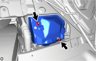
Install the No. 10 HV battery shield panel with the 2 nuts.
- Torque:
- 7.5 N*m { 76 kgf*cm, 66 in.*lbf }
-
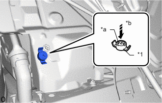
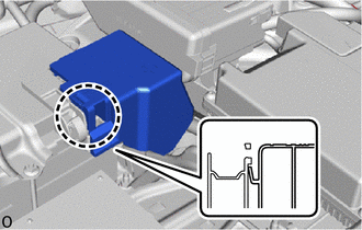
*1 Battery Cover Lock Striker *a Button *b Push Install the battery cover lock striker, then push the button to lock it.
-
-
CONNECT FLOOR WIRE
CAUTION:
Wear insulated gloves.
-
Connect the 2 connectors.
-
Attach the 2 claws and install the connector cover.
-
-
INSTALL NO. 4 HYBRID BATTERY INTAKE DUCT
-
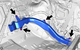
Install the No. 4 hybrid battery intake duct with the 4 clips.
-
-
INSTALL NO. 2 HYBRID BATTERY INTAKE DUCT
-
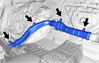
Install the No. 2 hybrid battery intake duct with the 4 clips.
-
-
INSTALL NO. 1 HYBRID BATTERY INTAKE DUCT
-
Install the No. 1 hybrid battery intake duct with the 2 clips.
-
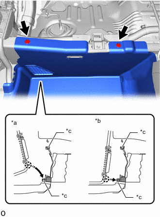
*a NG
(Installed in direction that will peel the sponge back)
*b OK
(Installed so that the sponge is squashed)
*c Sponge Connect the floor carpet mat assembly with the 2 clips.
Note
When securing the front floor carpet assembly RH, secure the sponge facing the front of the vehicle so that it becomes squashed and is not cut by the No. 1 hybrid battery intake duct.
-
-
INSTALL NO. 3 HYBRID BATTERY INTAKE DUCT
Tech Tips
Use the same procedure described for the No. 1 hybrid battery intake duct.
-
INSTALL QUARTER TRIM PANEL ASSEMBLY LH
-
INSTALL REAR INNER NO. 1 SEAT BELT ASSEMBLY LH
-
INSTALL QUARTER INSIDE TRIM BOARD LH
-
CONNECT FRONT OUTER SEAT BELT ASSEMBLY LH
-
INSTALL OUTER LAP BELT ANCHOR COVER
-
INSTALL FRONT DOOR SCUFF PLATE LH
-
INSTALL QUARTER TRIM PANEL ASSEMBLY RH
-
INSTALL REAR INNER SEAT BELT ASSEMBLY RH
Tech Tips
Use the same procedure described for the rear No. 1 seat inner belt assembly LH.
-
INSTALL QUARTER INSIDE TRIM BOARD RH
-
CONNECT FRONT OUTER SEAT BELT ASSEMBLY RH
-
INSTALL OUTER LAP BELT ANCHOR COVER
-
INSTALL FRONT DOOR SCUFF PLATE RH
-
INSTALL REAR SEAT SPEAKER
-
INSTALL REAR SEAT ASSEMBLY
-
INSTALL FRONT SEAT ASSEMBLY LH
-
INSTALL FRONT SEAT ASSEMBLY RH
Tech Tips
Use the same procedure described for the LH side.
-
INSTALL BATTERY CARRIER ASSEMBLY
-
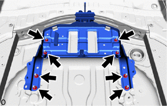
Install the battery carrier assembly with the 8 nuts.
- Torque:
- 7.0 N*m { 71 kgf*cm, 62 in.*lbf }
-
-
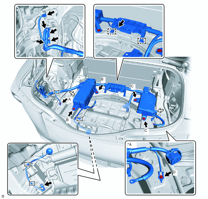
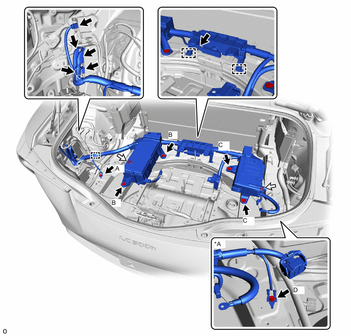
INSTALL NO. 1 LUGGAGE ROOM WIRE
-
w/ Canister Pump Module:
*A w/ Dynamic Rear Steering - -
-
Install the grommet and No. 1 luggage room wire.
-
Install the 2 nuts and attach the 6 clamps.
- Torque:
- 8.0 N*m { 82 kgf*cm, 71 in.*lbf }
-
w/ Dynamic Rear Steering:
Install the bolt (D).
- Torque:
- 10 N*m { 102 kgf*cm, 7 ft.*lbf }
-
Install the 2 bolts (C).
- Torque:
- 8.0 N*m { 82 kgf*cm, 71 in.*lbf }
-
Install the 2 bolts (B).
- Torque:
- 8.0 N*m { 82 kgf*cm, 71 in.*lbf }
-
Install the bolt (A).
- Torque:
- 10 N*m { 102 kgf*cm, 7 ft.*lbf }
-
Connect the 7 connectors.
-
-
w/o Canister Pump Module:
*A w/ Dynamic Rear Steering - -
-
Install the No. 1 luggage room wire.
-
Install the 2 nuts and attach the 3 clamps.
- Torque:
- 8.0 N*m { 82 kgf*cm, 71 in.*lbf }
-
w/ Dynamic Rear Steering:
Install the bolt (D).
- Torque:
- 10 N*m { 102 kgf*cm, 7 ft.*lbf }
-
Install the 2 bolts (C).
- Torque:
- 8.0 N*m { 82 kgf*cm, 71 in.*lbf }
-
Install the 2 bolts (B).
- Torque:
- 8.0 N*m { 82 kgf*cm, 71 in.*lbf }
-
Install the bolt (A).
- Torque:
- 10 N*m { 102 kgf*cm, 7 ft.*lbf }
-
Connect the 6 connectors.
-
-
-
INSTALL AUXILIARY BATTERY
-
INSTALL STEREO COMPONENT AMPLIFIER
-
INSTALL GROUND WIRE
-
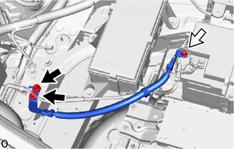
Install the ground wire with the 2 bolts and nut.
- Torque:
- Bolt
- 12.75 N*m { 130 kgf*cm, 9 ft.*lbf }
- Nut
- 7.55 N*m { 77 kgf*cm, 67 in.*lbf }
-
-
INSTALL ELECTRIC PARKING BRAKE ECU
-
INSTALL ACTIVE REAR WING ECU (w/ Active Rear Wing)
-
INSTALL BRAKE CONTROL POWER SUPPLY
-
INSTALL NO. 3 GROUND WIRE
-
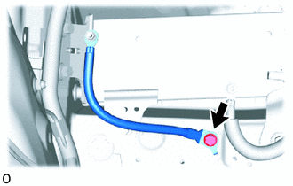
Install the No. 3 ground wire with the bolt.
- Torque:
- 12.75 N*m { 130 kgf*cm, 9 ft.*lbf }
-
-
INSTALL SUB-BATTERY MODULE ASSEMBLY
-
INSTALL DYNAMIC REAR STEERING ECU (w/ Dynamic Rear Steering)
-
CONNECT HV FLOOR UNDER WIRE
-
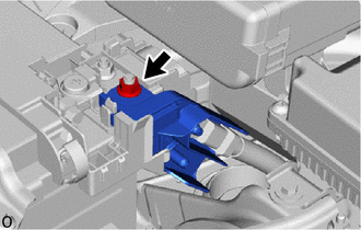
Connect the HV floor under wire with the nut.
- Torque:
- 7.55 N*m { 77 kgf*cm, 67 in.*lbf }
-
Attach the claw and install the battery terminal cover.
-
-
INSTALL SERVICE PLUG GRIP
-
CONNECT CABLE TO NEGATIVE AUXILIARY BATTERY TERMINAL
Note
When disconnecting the cable, some systems need to be initialized after the cable is reconnected.
-
INSTALL NO. 2 DECK BOARD
-
PERFORM UTILITY
Note
-
Perform "Battery Status Info Update" after replacing the malfunctioning HV battery.
-
Perform "Prediagnostic Battery Charge" after replacing the malfunctioning HV battery.
-
Perform "Battery Diagnosis" after replacing the malfunctioning HV battery.
-