BATTERY VOLTAGE SENSOR INSTALLATION
PROCEDURE
-
INSTALL BATTERY VOLTAGE SENSOR (for Lower Side)
CAUTION:
-
Be sure to wear insulated gloves and protective goggles.
-
Carry out safe work practices by connecting the No. 1 hybrid battery pack wire side connector first.
-
Install the battery voltage sensor (for lower side).
Note
-
Do not drop the battery voltage sensor (for lower side), strike it with tools or subject it to impact.
-
If the battery voltage sensor (for lower side) is subjected to an impact, replace it with a new one.
-
-
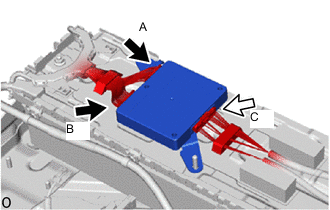
Connect connector C on the No. 1 hybrid battery pack wire side.
CAUTION:
Make sure to connect connector C on the No. 1 hybrid battery pack wire side first.
Note
Make sure that the connector is connected securely.
-
Connect connector A and connector B to the wire harness (No. 2 HV supply stack sub-assembly) cell voltage detection circuit.
CAUTION:
Make sure to connect connector C on the No. 1 hybrid battery pack wire side first.
Note
Make sure that the connector is connected securely.
-
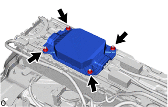
Install a new No. 1 HV battery protector (for lower side) with the 4 nuts.
- Torque:
- 7.5 N*m { 76 kgf*cm, 66 in.*lbf }
-
-
INSTALL UPPER HV BATTERY CARRIER SUB-ASSEMBLY
-
INSTALL HV BATTERY JUNCTION BLOCK ASSEMBLY
-
INSTALL NO. 6 HYBRID BATTERY INTAKE DUCT
-
INSTALL BATTERY COOLING BLOWER ASSEMBLY
-
INSTALL WIRE HARNESS CLAMP BRACKET
-
INSTALL NO. 8 HYBRID BATTERY INTAKE DUCT
-
INSTALL NO. 1 HV SUPPLY STACK SUB-ASSEMBLY
-
INSTALL NO. 7 HV BATTERY SHIELD SUB-ASSEMBLY (for Upper Side)
-
INSTALL BATTERY ECU ASSEMBLY
-
INSTALL BATTERY VOLTAGE SENSOR (for Upper Side)
CAUTION:
-
Be sure to wear insulated gloves and protective goggles.
-
Carry out safe work practices by connecting the No. 1 hybrid battery pack wire side connector first.
Tech Tips
A voltage equivalent to 1 stack (approximately 150 V) is output from the battery voltage sensor to the battery ECU assembly to detect malfunctions.
-
Install the battery voltage sensor (for upper side).
Note
-
Do not drop the battery voltage sensor (for upper side), strike it with tools or subject it to impact.
-
If the battery voltage sensor (for upper side) is subjected to an impact, replace it with a new one.
-
-
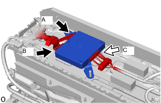
Connect connector C on the No. 1 hybrid battery pack wire side.
CAUTION:
Make sure to connect connector C on the No. 1 hybrid battery pack wire side first.
Note
Make sure that the connector is connected securely.
-
Connect connector A and connector B to the wire harness (No. 1 HV supply stack sub-assembly) cell voltage detection circuit.
CAUTION:
Make sure to connect connector C on the No. 1 hybrid battery pack wire side first.
Note
Make sure that the connector is connected securely.
-
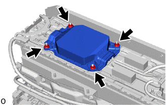
Install a new No. 1 HV battery protector (for upper side) with the 4 nuts.
- Torque:
- 7.5 N*m { 76 kgf*cm, 66 in.*lbf }
-
-
INSTALL NO. 1 HYBRID BATTERY EXHAUST DUCT
-
INSTALL UPPER NO. 1 HYBRID BATTERY COVER SUB-ASSEMBLY
-
INSTALL HYBRID BATTERY TERMINAL BLOCK
-
INSTALL NO. 1 HYBRID BATTERY SHIELD SUB-ASSEMBLY
-
INSTALL NO. 2 HYBRID BATTERY SHIELD SUB-ASSEMBLY
-
INSTALL UPPER HV BATTERY COVER PANEL
-
INSTALL HV BATTERY ASSEMBLY