FRAME WIRE INSTALLATION
PROCEDURE
-
INSTALL HV FLOOR UNDER WIRE
CAUTION:
Wear insulated gloves.
-
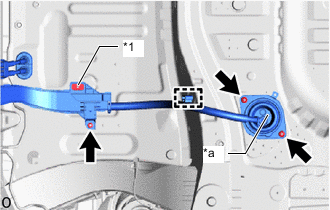
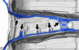
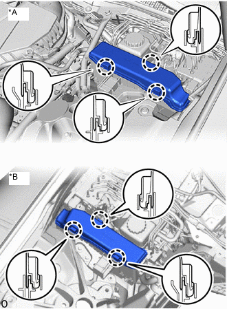
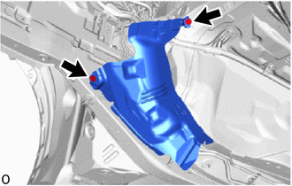
*1 Stud Clamp *a Arrow Pass the HV floor under wire through the cabin and install the 3 nuts.
- Torque:
- 8.0 N*m { 82 kgf*cm, 71 in.*lbf }
Note
Install the HV floor under wire in the direction of the arrow toward the front of the vehicle.
-
Attach the clamp.
Note
Securely attach the clamp.
-
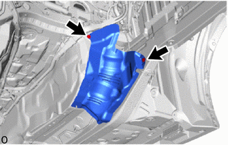
Install a new stud clamp.
-
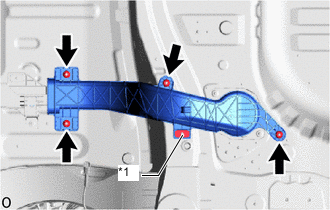
*1 Stud Clamp Install the wiring harness protector with the 4 nuts.
- Torque:
- 8.0 N*m { 82 kgf*cm, 71 in.*lbf }
-
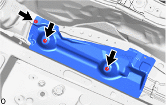
Install a new stud clamp.
-
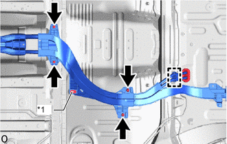
*1 Stud Clamp Pass the HV floor under wire through the cabin and install the grommet.
-
Install the 2 nuts.
- Torque:
- 8.0 N*m { 82 kgf*cm, 71 in.*lbf }
-
Install the 2 bolts.
- Torque:
- 13 N*m { 133 kgf*cm, 10 ft.*lbf }
-
Attach the clamp.
Note
Securely attach the clamp.
-
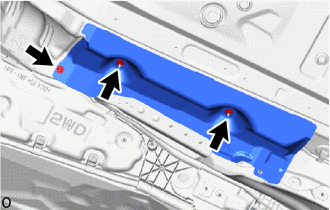
Install a new stud clamp.
-
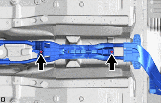
Install the 2 nuts.
- Torque:
- 8.0 N*m { 82 kgf*cm, 71 in.*lbf }
-
Install the 5 nuts.
- Torque:
- 8.0 N*m { 82 kgf*cm, 71 in.*lbf }
-
Attach the clamp.
Note
Securely attach the clamp.
-
Remove the connector cover assembly.
-
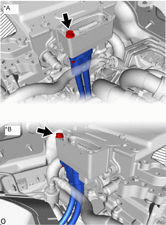
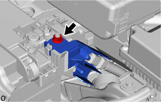
*A for LHD *B for RHD Connect the HV floor under wire.
Note
-
Do not allow any foreign matter or water to enter the inverter with converter assembly.
-
Do not touch the connector waterproofing rubber or terminals.
-
Do not damage the connector, connector housings or inverter with converter assembly during connection.
-
Make sure that the connector are fully engaged.
-
-
Install the bolt.
- Torque:
- 8.0 N*m { 82 kgf*cm, 71 in.*lbf }
-
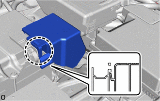
Install the connector cover assembly.
-
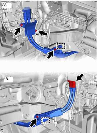
*A for LHD *B for RHD Attach the clamp.
-
Install the bolt.
- Torque:
- 8.0 N*m { 82 kgf*cm, 71 in.*lbf }
-
for LHD:
Install the wiring harness clamp bracket with the 2 nuts.
- Torque:
- 8.0 N*m { 82 kgf*cm, 71 in.*lbf }
-
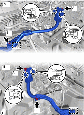
*A for LHD *B for RHD Attach the clamp.
-
Install the bolt B.
- Torque:
- 8.0 N*m { 82 kgf*cm, 71 in.*lbf }
-
Attach the 2 claws and connect the HV floor under wire to the engine room relay block.
-
Install the bolt A.
- Torque:
- 10 N*m { 102 kgf*cm, 7 ft.*lbf }
-
*A for LHD *B for RHD Attach the 3 claws and install the relay block cover.
-
Connect the HV floor under wire with the nut.
- Torque:
- 7.55 N*m { 77 kgf*cm, 67 in.*lbf }
-
Attach the claw and install the battery terminal connector cover.
-
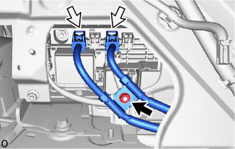
Connect the 2 connectors and install the nut.
- Torque:
- 8.0 N*m { 82 kgf*cm, 71 in.*lbf }
Note
Make sure that the connector is connected securely.
-
-
INSTALL FRONT NO. 1 FLOOR HEAT INSULATOR SUB-ASSEMBLY
-
Install the front No. 1 floor heat insulator sub-assembly with the 2 bolts.
- Torque:
- 5.4 N*m { 55 kgf*cm, 48 in.*lbf }
-
-
INSTALL FRONT NO. 2 FLOOR HEAT INSULATOR SUB-ASSEMBLY
-
Install the front No. 2 floor heat insulator sub-assembly with the 2 bolts.
- Torque:
- 5.4 N*m { 55 kgf*cm, 48 in.*lbf }
-
-
INSTALL FRONT NO. 5 FLOOR HEAT INSULATOR
-
Install the front No. 5 floor heat insulator with the 3 nuts.
- Torque:
- 5.4 N*m { 55 kgf*cm, 48 in.*lbf }
-
-
INSTALL FRONT NO. 6 FLOOR HEAT INSULATOR
-
Install the front No. 6 floor heat insulator with the 3 nuts.
- Torque:
- 5.4 N*m { 55 kgf*cm, 48 in.*lbf }
-
-
INSTALL NO. 10 HV BATTERY SHIELD PANEL
-
INSTALL NO. 2 HYBRID BATTERY INTAKE DUCT
-
INSTALL NO. 1 HYBRID BATTERY INTAKE DUCT
-
INSTALL QUARTER TRIM PANEL ASSEMBLY RH
-
INSTALL REAR INNER SEAT BELT ASSEMBLY RH
Tech Tips
Use the same procedure described for the rear No. 1 seat inner belt assembly LH.
-
INSTALL QUARTER INSIDE TRIM BOARD RH
-
CONNECT FRONT OUTER SEAT BELT ASSEMBLY RH
-
INSTALL OUTER LAP BELT ANCHOR COVER
-
INSTALL FRONT DOOR SCUFF PLATE RH
-
INSTALL REAR SEAT SPEAKER
-
INSTALL REAR SEAT ASSEMBLY
-
INSTALL FRONT SEAT ASSEMBLY RH
-
INSTALL FUEL TANK ASSEMBLY
-
w/ Canister Pump Module:
-
w/o Canister Pump Module:
-
-
INSTALL ENGINE ASSEMBLY WITH TRANSMISSION
-
INSTALL SERVICE PLUG GRIP
-
CONNECT CABLE TO NEGATIVE AUXILIARY BATTERY TERMINAL
Note
When disconnecting the cable, some systems need to be initialized after the cable is reconnected.
-
INSTALL NO. 2 DECK BOARD