SUB RADIATOR INSTALLATION
PROCEDURE
-
INSTALL RADIATOR ASSEMBLY (for Inverter Coolant)
-
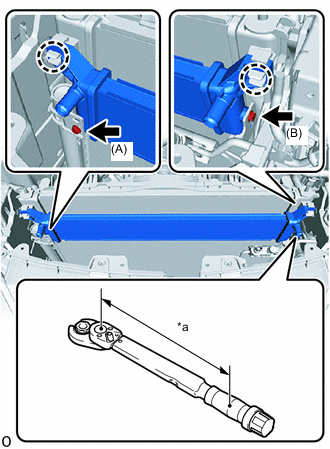
*a Torque Wrench Fulcrum Length Attach the 2 claws and install the radiator assembly.
-
Install the bolt A.
- Torque:
- 9.0 N*m { 92 kgf*cm, 80 in.*lbf }
-
Using a 10 mm union nut wrench, install the bolt B.
- Torque:
- Specified tightening torque
- 9.0 N*m { 92 kgf*cm, 80 in.*lbf }
Tech Tips
-
Calculate the torque wrench reading when changing the fulcrum length of the torque wrench.
-
When using a union nut wrench (fulcrum length of 22 mm (0.866 in.)) + torque wrench (fulcrum length of 162 mm (6.378 in.)): 7.9 N*m (81 kgf*cm, 70 in.*lbf)
-
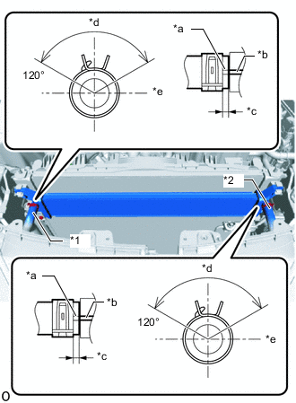
*1 No. 2 Inverter Cooling Hose *2 No. 3 Inverter Cooling Hose *a Alignment Mark (Yellow) *b Rib *c 2.0 to 5.0 mm (0.079 to 0.196 in.) *d Upper Side *e LH Side Connect the No. 2 inverter cooling hose and No. 3 inverter cooling hose to the radiator assembly and slide the 2 hose clips to secure them.
Note
To prevent foreign matter from entering the radiator assembly and inverter cooling system, do not remove the pieces of cloth from the pipes and disconnected hoses until installation.
Tech Tips
-
Make sure to align the alignment marks of the hoses with the ribs of the radiator assembly.
-
Make sure that the clips are positioned as shown in the illustration.
-
-
-
INSTALL UPPER RADIATOR SUPPORT SUB-ASSEMBLY
-
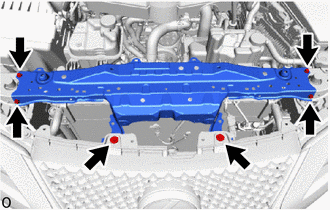
Install the upper radiator support sub-assembly with the 4 bolts.
- Torque:
- 12.5 N*m { 127 kgf*cm, 9 ft.*lbf }
-
Install the 2 clips.
-
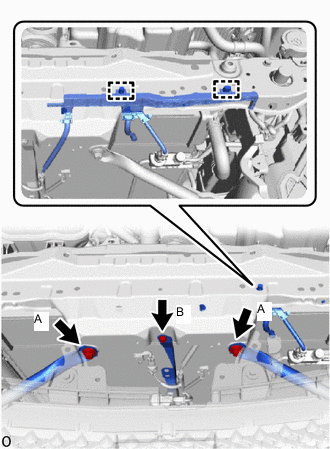
Attach the 2 clamps to connect the engine room main wire.
-
Install the 3 bolts.
- Torque:
- Bolt A
- 20 N*m { 204 kgf*cm, 15 ft.*lbf }
- Bolt B
- 12.5 N*m { 127 kgf*cm, 9 ft.*lbf }
-
-
INSTALL LOW PITCHED HORN ASSEMBLY
-
INSTALL HOOD LOCK ASSEMBLY
-
INSTALL HOOD LOCK CONTROL CABLE COVER LH (for LHD)
-
INSTALL HOOD LOCK CONTROL CABLE COVER RH
Tech Tips
Use the same procedure described for the LH side.
-
INSTALL HOOD LOCK RELEASE LEVER PROTECTOR
-
INSTALL NO. 1 AIR CLEANER INLET
-
INSTALL RADIATOR SUPPORT TO CROSSMEMBER BRACE SUB-ASSEMBLY LH
-
INSTALL RADIATOR SUPPORT TO CROSSMEMBER BRACE SUB-ASSEMBLY RH
-
INSTALL LOWER RADIATOR AIR DEFLECTOR
-
INSTALL RADIATOR SUPPORT TO FRAME SEAL RH
-
ADD COOLANT (for Inverter)
-
INSPECT FOR COOLANT LEAK (for Inverter)