HYBRID CONTROL SYSTEM Oil Pump Motor Circuit
DESCRIPTION
The cause of the malfunction may be the electric oil pump motor system.
Check that there are no problems in the signal line between the oil pump motor controller and hybrid vehicle control ECU assembly and that there is no short to +B, open or short in the oil pump motor controller power source.
| Area | Inspection | Step |
|---|---|---|
| Wire harness and connector between oil pump motor controller and hybrid vehicle control ECU assembly | Check for open or short in wire harness and check connector connection condition | 1, 2, 3 |
| Check oil pump motor controller assembly power source system | Check oil pump motor controller assembly power source system | 4, 5, 6 |
| Oil with motor pump assembly | Check for open or short to +B in power supply of the oil pump with motor assembly | 7 |
| Perform Simulation Test | - | 8, 9, 10, 11 |
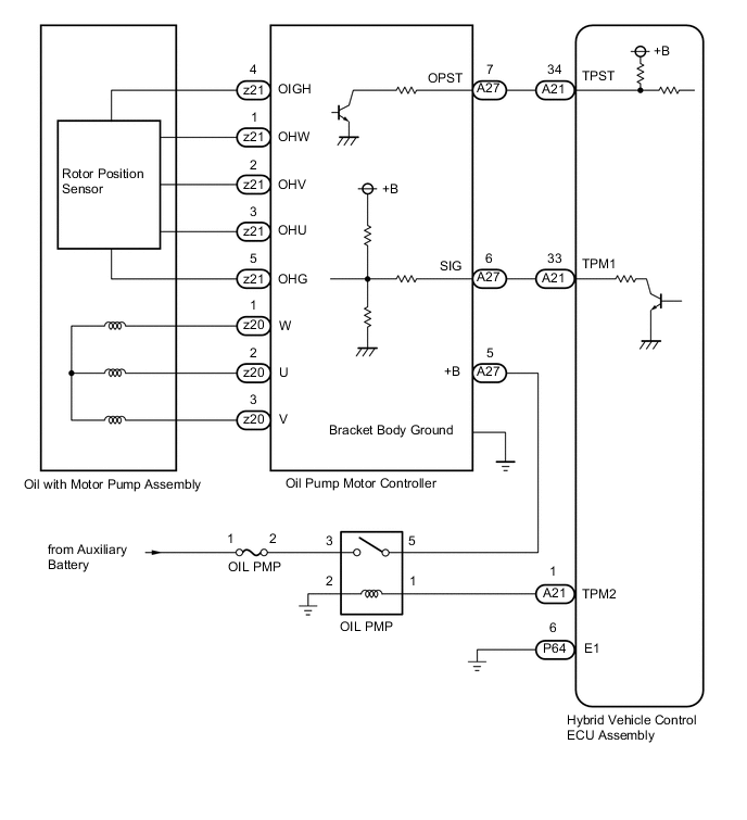
WIRING DIAGRAM
CAUTION / NOTICE / HINT
This procedure is referenced from the procedures for each DTC.
If the following inspection results are normal, perform the next procedure for the referenced DTC.
PROCEDURE
-
CHECK CONNECTOR CONNECTION CONDITION (OIL PUMP MOTOR CONTROLLER CONNECTOR)
Result Proceed to OK NG Note
Before disconnecting the connector, confirm that it is properly connected by checking that the claws of the lock levers are engaged and that the connector cannot be pulled off.
-
Check the connection condition of the oil pump motor controller connector.
OK The connectors are connected securely and there are no contact pressure problems. Tech Tips
When connecting the connector, connect it with the lock levers raised. Rotate each lock lever downward and make sure that the connector is securely connected. When a lock lever is fully lowered, a click will be heard as its claw engages. After the click is heard, pull up on the connector to confirm that it is securely connected.
Result Proceed to OK NG
NG 
CONNECT SECURELY
OK 
-
-
CHECK CONNECTOR CONNECTION CONDITION (HYBRID VEHICLE CONTROL ECU ASSEMBLY CONNECTOR)
Result Proceed to OK NG
-
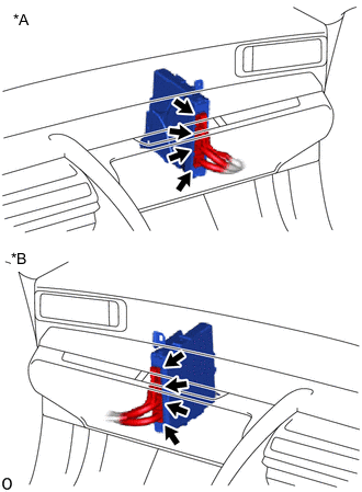
*A for LHD *B for RHD Check the connector connections and contact pressure of the relevant terminals for the hybrid vehicle control ECU assembly connectors.
OK The connectors are connected securely and there are no contact pressure problems. Result Proceed to OK NG
NG
CONNECT SECURELY
OK
-
-
CHECK HARNESS AND CONNECTOR (HYBRID VEHICLE CONTROL ECU ASSEMBLY - OIL PUMP MOTOR CONTROLLER)
-
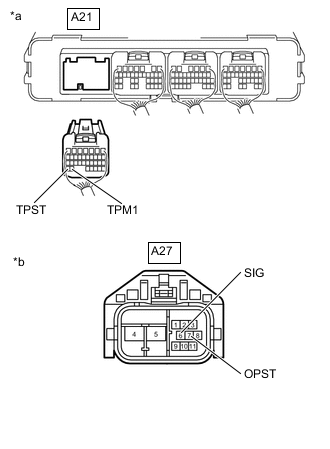
*a Rear view of wire harness connector
(to Hybrid Vehicle Control ECU Assembly)
*b Front view of wire harness connector
(to Oil Pump Motor Controller)
Disconnect the hybrid vehicle control ECU assembly connector.
-
Disconnect the oil pump motor controller connector.
-
Turn the power switch on (IG).
-
Measure the voltage according to the value(s) in the table below.
Standard Voltage Tester Connection Condition Specified Condition A21-33 (TPM1) - Body ground Power switch on (IG) Below 1 V A21-34 (TPST) - Body ground Power switch on (IG) Below 1 V Note
Turning the power switch on (IG) with the hybrid vehicle control ECU assembly connector and the oil pump motor controller connector disconnected causes other DTCs to be stored. Clear the DTCs after performing this inspection.
-
Turn the power switch off.
-
Measure the resistance according to the value(s) in the table below.
Standard Resistance Tester Connection Condition Specified Condition A21-33 (TPM1) - A27-6 (SIG) Power switch off Below 1 Ω A21-34 (TPST) - A27-7 (OPST) Power switch off Below 1 Ω A21-33 (TPM1) - Body ground and other terminals Power switch off 10 kΩ or higher A21-34 (TPST) - Body ground and other terminals Power switch off 10 kΩ or higher -
Reconnect the hybrid vehicle control ECU assembly connector.
-
Reconnect the oil pump motor controller connector.
Result Proceed to OK NG
NG
REPAIR OR REPLACE HARNESS OR CONNECTOR
OK
-
-
CHECK FUSIBLE LINK (OIL PMP)
-
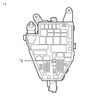
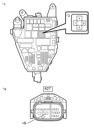
*1 No. 1 Engine Room Relay Block *2 Fusible Link (OIL PMP) Check if there is an open circuit in the fusible link (OIL PMP) in the No. 1 engine room relay block.
OK There is no open circuit in the fusible link (OIL PMP). Result Proceed to OK NG
NG
REPLACE FUSIBLE LINK (OIL PMP)
OK
-
-
INSPECT RELAY (OIL PMP)
-
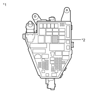
*1 No. 1 Engine Room Relay Block *2 OIL PMP Relay Remove the OIL PMP relay from the No. 1 engine room relay block.
-
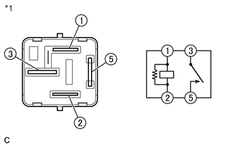
*1 OIL PMP Relay Measure the resistance according to the value(s) in the table below.
Standard Resistance Tester Connection Condition Specified Condition 1 - 2 Always 151 to 203 Ω 3 - 5 Auxiliary battery voltage not applied between terminals 1 and 2 10 kΩ or higher Auxiliary battery voltage applied between terminals 1 and 2 Below 1 Ω -
Install the OIL PMP relay.
Result Proceed to OK NG
NG
REPLACE RELAY (OIL PMP)
OK
-
-
CHECK OIL PUMP MOTOR CONTROLLER (POWER SOURCE CIRCUIT)
-
Disconnect the oil pump motor controller connector.
-
Turn the power switch on (IG).
-
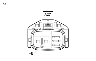
*a Front view of wire harness connector
(to Oil Pump Motor Controller)
Measure the voltage according to the value(s) in the table below.
Standard Voltage Tester Connection Condition Specified Condition A27-5 (+B) - Body ground Power switch on (IG) 11 to 14 V -
Turn the power switch off.
-
*1 No. 1 Engine Room Relay Block *2 OIL PMP Relay Remove the OIL PMP relay from the No. 1 engine room relay block.
-
*1 No. 1 Engine Room Relay Block *2 OIL PMP Relay *a Front view of wire harness connector
(to Oil Pump Motor Controller)
Measure the resistance according to the value(s) in the table below.
Standard Resistance Tester Connection Condition Specified Condition 5 - A27-5 (+B) Power switch off Below 1 Ω 2 - Body ground Power switch off Below 1 Ω 5 - Body ground Power switch off 10 kΩ or higher -
Disconnect the hybrid vehicle control ECU assembly connector.
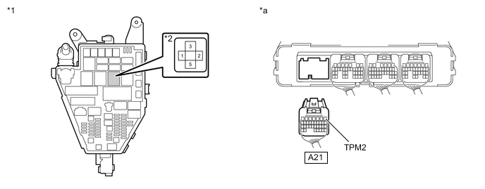
*1 No. 1 Engine Room Relay Block *2 OIL PMP Relay *a Rear view of wire harness connector
(to Hybrid Vehicle Control ECU Assembly)
- - -
Turn the power switch off.
-
Measure the resistance according to the value(s) in the table below.
Standard Resistance Tester Connection Condition Specified Condition 1 - A21-1 (TPM2) Power switch off Below 1 Ω 1 o A21-1 (TPM2) - Body ground Power switch off 10 kΩ or higher -
Reconnect the oil pump motor controller connector.
-
Install the OIL PMP relay.
-
Reconnect the hybrid vehicle control ECU assembly connector.
Result Proceed to OK NG
NG
REPAIR OR REPLACE HARNESS OR CONNECTOR
OK
-
-
CHECK OIL WITH MOTOR PUMP ASSEMBLY
-
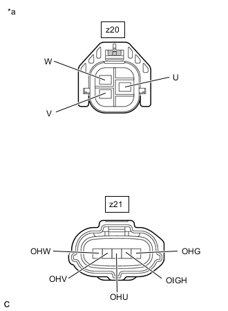
*a Front view of wire harness connector
(to Oil Pump Motor Controller)
Disconnect the oil pump motor controller connector.
-
Turn the power switch off.
-
Measure the voltage according to the value(s) in the table below.
Standard Voltage Tester Connection Condition Specified Condition z20-1 (W) - Body ground Power switch on (IG) Below 1 V z20-2 (U) - Body ground Power switch on (IG) Below 1 V z20-3 (V) - Body ground Power switch on (IG) Below 1 V z21-1 (OHW) - Body ground Power switch on (IG) Below 1 V z21-2 (OHV) - Body ground Power switch on (IG) Below 1 V z21-3 (OHU) - Body ground Power switch on (IG) Below 1 V z21-4 (OIGH) - Body ground Power switch on (IG) Below 1 V z21-5 (OHG) - Body ground Power switch on (IG) Below 1 V Note
Turning the power switch on (IG) with the oil pump motor controller connector disconnected causes other DTCs to be stored. Clear the DTCs after performing this inspection.
-
Turn the power switch off.
-
Measure the resistance according to the value(s) in the table below.
Standard Resistance Tester Connection Condition Specified Condition z20-1 (W) - z20-2 (U) Power switch off Below 1 Ω z20-1 (W) - z20-3 (V) Power switch off Below 1 Ω z20-1 (W) - Body ground Power switch off 10 kΩ or higher z20-2 (U) - Body ground Power switch off 10 kΩ or higher z20-3 (V) - Body ground Power switch off 10 kΩ or higher z21-1 (OHW) - Body ground Power switch off 10 kΩ or higher z21-2 (OHV) - Body ground Power switch off 10 kΩ or higher z21-3 (OHU) - Body ground Power switch off 10 kΩ or higher z21-4 (OIGH) - Body ground Power switch off 10 kΩ or higher z21-5 (OHG) - Body ground Power switch off 10 kΩ or higher -
Reconnect the oil pump motor controller connector.
Result Proceed to OK NG
NG
REPLACE OIL WITH MOTOR PUMP ASSEMBLY Click here
OK
-
-
CLEAR DTC
-
Connect the GTS to the DLC3.
-
Turn the power switch on (IG).
-
Enter the following menus: Powertrain / Hybrid Control / Trouble Codes.
Powertrain > Hybrid Control > Clear DTCs -
Read and record the DTCs and freeze frame data.
-
Clear the DTCs.
-
Turn the power switch off.
Result Proceed to NEXT
NEXT
-
-
SIMULATION TEST
-
Connect the GTS to the DLC3.
-
Turn the power switch on (IG).
-
Enter the following menus: Powertrain / Motor Generator Control / Active Test / Control the Transmission Oil Pump.
Powertrain > Hybrid Control > Active TestTester Display Control the Transmission Oil Pump -
Select the Data List item "Transmission Fluid Pump Motor Revolution".
Powertrain > Hybrid Control > Data ListTester Display Transmission Fluid Pump Motor Revolution -
Perform the Active Test.
OK When the transmission oil pump Active Test is performed, the value of the Data List item "Transmission Fluid Pump Motor Revolution" is approximately the same as each commanded speed. Transmission Oil Pump Transmission Fluid Pump Motor Revolution 500 rpm 400 to 700 rpm 1000 rpm 900 to 1200 rpm Note
Make sure that the auxiliary battery does not deplete.
-
Turn the power switch off.
Result Proceed to OK NG
NG
REPLACE OIL WITH MOTOR PUMP ASSEMBLY Click here
OK
-
-
CHECK INTERMITTENT PROBLEMS
Result Proceed to OK NG
NG
REPAIR OR REPLACE MALFUNCTIONING PARTS, COMPONENT AND AREA
OK
-
CHECK FLUID LEAKS
-
Check the hybrid vehicle transmission assembly for fluid leaks.
OK No fluid leaks. Result Proceed to OK NG
OK
OIL PUMP MOTOR CIRCUIT NORMAL (PERFORM NEXT STEP FOR REFERENCED DTC)
NG
REPLACE HYBRID VEHICLE TRANSMISSION ASSEMBLY Click here
-