MOTOR GENERATOR CONTROL SYSTEM TERMINALS OF ECU
-
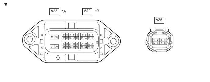
*A for LHD *B for RHD *a Inverter with Converter Assembly - - Tech Tips
Since the inverter with converter assembly uses waterproof connectors, the voltage and waveforms cannot be inspected directly. Standard voltage readings and waveforms are indicated for reference only.
Inverter with Converter Assembly (for LHD) Terminal No.
(Symbol)
Wiring Color Input/Output Terminal Description Condition Standard Condition A23-1 (MSN) - A23-2 (MSNG) Y - G Input Motor resolver signal Motor resolver running Pulse generation
(Waveform 1)
A23-3 (MCSG) - A23-4 (MCS) W - R Input Motor resolver signal Motor resolver running Pulse generation
(Waveform 1)
A23-5 (HMCH) - A23-30 (GND1) W - W-B Input/Output Communication signal Power switch on (IG) Pulse generation
(Waveform 2)
A23-6 (HMCL) - A23-30 (GND1) B - W-B Input/Output Communication signal Power switch on (IG) Pulse generation
(Waveform 2)
A23-9 (GI) - A23-30 (GND1) W - W-B Input Camshaft position sensor signal Power switch on (READY), engine running Pulse generation
(Waveform 3)
A23-10 (+B) - A23-30 (GND1) B - W-B Input Motor generator control ECU (MG ECU) power source Power switch on (IG) 11 to 14 V A23-11 (+B2) - A23-30 (GND1) B - W-B Input Motor generator control ECU (MG ECU) power source Power switch on (IG) 11 to 14 V A23-12 (MRF) - A23-23 (MRFG) L - B Output Motor resolver reference signal Motor resolver running Pulse generation
(Waveform 1)
A23-20 (NE) - A23-30 (GND1) B - W-B Input Crankshaft position sensor signal Power switch on (READY), engine running Pulse generation
(Waveform 4)
A23-21 (GRF) - A23-14 (GRFG) G - Y Output Generator resolver reference signal Generator resolver running Pulse generation
(Waveform 5)
A23-25 (CANH) - A23-30 (GND1) GR - W-B Input/Output CAN communication signal Power switch on (IG) Pulse generation
(Waveform 6)
A23-32 (GSN) - A23-33 (GSNG) B - L Input Generator resolver signal Generator resolver running Pulse generation
(Waveform 5)
A23-34 (GCSG) - A23-35 (GCS) W - R Input Generator resolver signal Generator resolver running Pulse generation
(Waveform 5)
A23-36 (CANL) - A23-30 (GND1) BR - W-B Input/Output CAN communication signal Power switch on (IG) Pulse generation
(Waveform 6)
A23-40 (HSDN) - A23-30 (GND1) B - W-B Input MG shutdown signal Power switch on (READY) 0 to 1 V A25-1 (IGCT) - A23-30 (GND1) L - W-B Input Motor generator control ECU (MG ECU) power source Power switch on (IG) 11 to 14 V A25-2 (IDH) - A23-30 (GND1) Y - W-B Output PTC heater prohibit signal Power switch on (IG) 4 to 6 V A25-3 (S) - A23-30 (GND1) B - W-B Input Auxiliary battery voltage monitor Power switch on (IG) 11 to 14 V A25-5 (NODD) - A23-30 (GND1) V - W-B Input/Output DC/DC operation DC/DC converter operating normally 5 to 7 V DC/DC converter not operating normally 2 to 4 V DC/DC converter operation prohibited 0.1 to 0.5 V A25-6 (VLO) - A23-30 (GND1) W - W-B Input DC/DC operation monitor/voltage change signal Power switch on (IG) Pulse generation
(Waveform 7)
Inverter with Converter Assembly (for RHD) Terminal No.
(Symbol)
Wiring Color Input/Output Terminal Description Condition Standard Condition A24-1 (MSN) - A24-2 (MSNG) Y - G Input Motor resolver signal Motor resolver running Pulse generation
(Waveform 1)
A24-3 (MCSG) - A24-4 (MCS) W - R Input Motor resolver signal Motor resolver running Pulse generation
(Waveform 1)
A24-5 (HMCH) - A24-30 (GND1) W - W-B Input/Output Communication signal Power switch on (IG) Pulse generation
(Waveform 2)
A24-6 (HMCL) - A24-30 (GND1) B - W-B Input/Output Communication signal Power switch on (IG) Pulse generation
(Waveform 2)
A24-9 (GI) - A24-30 (GND1) W - W-B Input Camshaft position sensor signal Power switch on (READY), engine running Pulse generation
(Waveform 3)
A24-10 (+B) - A24-30 (GND1) B - W-B Input Motor generator control ECU (MG ECU) power source Power switch on (IG) 11 to 14 V A24-11 (+B2) - A24-30 (GND1) B - W-B Input Motor generator control ECU (MG ECU) power source Power switch on (IG) 11 to 14 V A24-12 (MRF) - A24-23 (MRFG) L - B Output Motor resolver reference signal Motor resolver running Pulse generation
(Waveform 1)
A24-20 (NE) - A24-30 (GND1) B - W-B Input Crankshaft position sensor signal Power switch on (READY), engine running Pulse generation
(Waveform 4)
A24-21 (GRF) - A24-14 (GRFG) G - Y Output Generator resolver reference signal Generator resolver running Pulse generation
(Waveform 5)
A24-25 (CANH) - A24-30 (GND1) GR - W-B Input/Output CAN communication signal Power switch on (IG) Pulse generation
(Waveform 6)
A24-32 (GSN) - A24-33 (GSNG) B - L Input Generator resolver signal Generator resolver running Pulse generation
(Waveform 5)
A24-34 (GCSG) - A24-35 (GCS) W - R Input Generator resolver signal Generator resolver running Pulse generation
(Waveform 5)
A24-36 (CANL) - A24-30 (GND1) BR - W-B Input/Output CAN communication signal Power switch on (IG) Pulse generation
(Waveform 6)
A24-40 (HSDN) - A24-30 (GND1) B - W-B Input MG shutdown signal Power switch on (READY) 0 to 1 V A25-1 (IGCT) - A24-30 (GND1) L - W-B Input Motor generator control ECU (MG ECU) power source Power switch on (IG) 11 to 14 V A25-2 (IDH) - A24-30 (GND1) Y - W-B Output PTC heater prohibit signal Power switch on (IG) 4 to 6 V A25-3 (S) - A24-30 (GND1) B - W-B Input Auxiliary battery voltage monitor Power switch on (IG) 11 to 14 V A25-5 (NODD) - A24-30 (GND1) V - W-B Input/Output DC/DC operation DC/DC converter operating normally 5 to 7 V DC/DC converter not operating normally 2 to 4 V DC/DC converter operation prohibited 0.1 to 0.5 V A25-6 (VLO) - A24-30 (GND1) W - W-B Input DC/DC operation monitor/voltage change signal Power switch on (IG) Pulse generation
(Waveform 7)
Note
Do not measure the voltage or waveform on the sealed side of the inverter with converter assembly connector. Doing so may damage the connector because the connector is waterproof.
-
Oscilloscope waveforms
Tech Tips
Oscilloscope waveforms shown in the illustrations are examples for reference only. Noise, chattering, etc. are not shown.
-

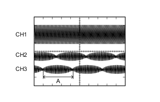
Waveform 1 (motor resolver signal)
for LHD Item Content Terminal CH1: A23-12 (MRF) - A23-23 (MRFG)
CH2: A23-1 (MSN) - A23-2 (MSNG)
CH3: A23-4 (MCS) - A23-3 (MCSG)
Equipment Setting CH1: 10 V/DIV., 1 ms./DIV.
CH2: 5 V/DIV., 1 ms./DIV.
CH3: 5 V/DIV., 1 ms./DIV.
Condition Motor resolver running for RHD Item Content Terminal CH1: A24-12 (MRF) - A24-23 (MRFG)
CH2: A24-1 (MSN) - A24-2 (MSNG)
CH3: A24-4 (MCS) - A24-3 (MCSG)
Equipment Setting CH1: 10 V/DIV., 1 ms./DIV.
CH2: 5 V/DIV., 1 ms./DIV.
CH3: 5 V/DIV., 1 ms./DIV.
Condition Motor resolver running Tech Tips
The width indicated by (A) becomes shorter as the rotor speed increases.
-

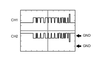
Waveform 2 (communication signal)
for LHD Item Content Terminal CH1: A23-6 (HMCL) - A23-30 (GND1)
CH2: A23-5 (HMCH) - A23-30 (GND1)
Equipment Setting 1 V/DIV., 50 μs./DIV. Condition Power switch on (IG) for RHD Item Content Terminal CH1: A24-6 (HMCL) - A24-30 (GND1)
CH2: A24-5 (HMCH) - A24-30 (GND1)
Equipment Setting 1 V/DIV., 50 μs./DIV. Condition Power switch on (IG) Tech Tips
The waveform will vary depending on the content of the digital communication (digital signal).
-
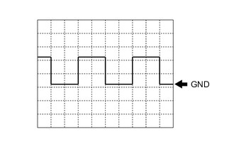
Waveform 3 (camshaft position sensor signal)
for LHD Item Content Terminal A23-9 (GI) - A23-30 (GND1) Equipment Setting 5 V/DIV., 20 ms./DIV. Condition Power switch on (READY), engine running for RHD Item Content Terminal A24-9 (GI) - A24-30 (GND1) Equipment Setting 5 V/DIV., 20 ms./DIV. Condition Power switch on (READY), engine running Tech Tips
The wavelength becomes shorter as the engine speed increases.
-

Waveform 4 (crankshaft position sensor signal)
for LHD Item Content Terminal A23-20 (NE) - A23-30 (GND1) Equipment Setting 5 V/DIV., 20 ms./DIV. Condition Power switch on (READY), engine running for RHD Item Content Terminal A24-20 (NE) - A24-30 (GND1) Equipment Setting 5 V/DIV., 20 ms./DIV. Condition Power switch on (READY), engine running Tech Tips
The wavelength becomes shorter as the engine speed increases.
-
Waveform 5 (generator resolver signal)
for LHD Item Content Terminal CH1: A23-21 (GRF) - A23-14 (GRFG)
CH2: A23-32 (GSN) - A23-33 (GSNG)
CH3: A23-35 (GCS) - A23-34 (GCSG)
Equipment Setting CH1: 10 V/DIV., 1 ms./DIV.
CH2: 5 V/DIV., 1 ms./DIV.
CH3: 5 V/DIV., 1 ms./DIV.
Condition Generator resolver running for RHD Item Content Terminal CH1: A24-21 (GRF) - A24-14 (GRFG)
CH2: A24-32 (GSN) - A24-33 (GSNG)
CH3: A24-35 (GCS) - A24-34 (GCSG)
Equipment Setting CH1: 10 V/DIV., 1 ms./DIV.
CH2: 5 V/DIV., 1 ms./DIV.
CH3: 5 V/DIV., 1 ms./DIV.
Condition Generator resolver running Tech Tips
The width indicated by (A) becomes shorter as the rotor speed increases.
-
Waveform 6 (CAN communication signal)
for LHD Item Content Terminal CH1: A23-25 (CANH) - A23-30 (GND1)
CH2: A23-36 (CANL) - A23-30 (GND1)
Equipment Setting 1 V/DIV., 50 μs./DIV. Condition Power switch on (IG) for RHD Item Content Terminal CH1: A24-25 (CANH) - A24-30 (GND1)
CH2: A24-36 (CANL) - A24-30 (GND1)
Equipment Setting 1 V/DIV., 50 μs./DIV. Condition Power switch on (IG) -
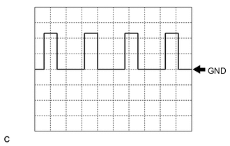
Waveform 7 (DC/DC operation monitor/voltage change signal)
for LHD Item Content Terminal A25-6 (VLO) - A23-30 (GND1) Equipment Setting 5 V/DIV., 50 ms./DIV. Condition Power switch on (IG) for RHD Item Content Terminal A25-6 (VLO) - A24-30 (GND1) Equipment Setting 5 V/DIV., 50 ms./DIV. Condition Power switch on (IG) Tech Tips
The cycle will vary depending on the specified voltage of the hybrid vehicle converter.
-