HYBRID CONTROL SYSTEM Solenoid Valve Circuit
DESCRIPTION
The cause of this malfunction may be the motor resolver.
Check the installation condition of the solenoids installed to each solenoid valve and transmission valve body.
| Area | Inspection | Step |
|---|---|---|
| Solenoid valve | Check internal resistance of each solenoid valve | 1, 2, 3 |
| Transmission valve body assembly | Check solenoid installation conditions | 4 |
CAUTION / NOTICE / HINT
This procedure is referenced from the procedures for each DTC.
If the following inspection results are normal, perform the next procedure for the referenced DTC.
PROCEDURE
-
INSPECT SOLENOID (SL1), (SL2), (SL3) AND (SL4) VALVE
-
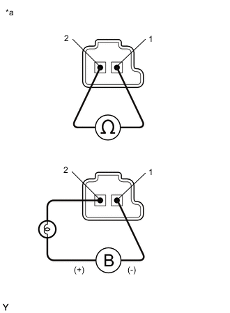
*a Component without harness connected
(Solenoid (SL1), (SL2), (SL3) and (SL4) Valves)
Remove the solenoid (SL1), (SL2), (SL3) and (SL4) valves.
-
Measure the resistance according to the value(s) in the table below.
Standard Resistance Tester Connection Condition Specified Condition Terminal 1 of the solenoid (SL1) valve - terminal 2 20°C (68°F) 5.0 to 5.6 Ω Terminal 1 of the solenoid (SL2) valve - terminal 2 20°C (68°F) 5.0 to 5.6 Ω Terminal 1 of the solenoid (SL3) valve - terminal 2 20°C (68°F) 5.0 to 5.6 Ω Terminal 1 of the solenoid (SL4) valve - terminal 2 20°C (68°F) 5.0 to 5.6 Ω -
Connect a positive (+) lead from the battery with a 21 W bulb to terminal 2 and a negative (-) lead to terminal 1 of the solenoid valve connector. Check that the valve moves and makes an operating sound.
OK Valve moves and makes an operating sound. -
Install the solenoid (SL1), (SL2), (SL3) and (SL4) valves.
Result Proceed to OK NG
NG 
REPLACE SOLENOID (SL1), (SL2), (SL3) OR (SL4) VALVE Click here
OK 
-
-
INSPECT SOLENOID (SC1) AND (SC2) VALVE
-
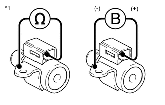
*1 Solenoid (SC1) and (SC2) Valves Remove the solenoid (SC1) and (SC2) valves.
-
Measure the resistance according to the value(s) in the table below.
Standard Resistance Tester Connection Condition Specified Condition Terminal of solenoid (SC1) valve connector - Solenoid (SC1) valve body 20°C (68°F) 11 to 15 Ω Terminal of solenoid (SC2) valve connector - Solenoid (SC2) valve body 20°C (68°F) 11 to 15 Ω -
Connect a positive (+) lead from the battery to the terminal of the solenoid valve connector, and a negative (-) lead to the solenoid body. Check that the valve moves and makes an operating sound.
OK Valve moves and makes an operating sound. -
Install the solenoid (SC1) and (SC2) valves.
Result Proceed to OK NG
NG
REPLACE SOLENOID (SC1) OR (SC2) VALVE Click here
OK
-
-
INSPECT SOLENOID (SLT) VALVE
-
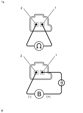
*a Component without harness connected
(Solenoid (SLT) Valve)
Remove the solenoid (SLT) valve.
-
Measure the resistance according to the value(s) in the table below.
Standard Resistance Tester Connection Condition Specified Condition Terminal 1 of the solenoid (SLT) valve - terminal 2 20°C (68°F) 5.0 to 5.6 Ω -
Connect a positive (+) lead from the battery with a 21 W bulb to terminal 1 and a negative (-) lead to terminal 2 of the solenoid valve connector. Check that the valve moves and makes an operating sound.
OK Valve moves and makes an operating sound. -
Install the solenoid (SLT) valve.
Result Proceed to OK NG
NG
REPLACE SOLENOID (SLT) VALVE Click here
OK
-
-
INSPECT TRANSMISSION VALVE BODY ASSEMBLY
-
Check the transmission valve body assembly.
OK There is no foreign matter on each valve and they operate smoothly. Result Proceed to OK NG
OK
SOLENOID VALVE CIRCUIT NORMAL (PERFORM NEXT STEP FOR REFERENCED DTC)
NG
REPAIR OR REPLACE TRANSMISSION VALVE BODY ASSEMBLY Click here
-