HYBRID CONTROL SYSTEM DIAGNOSIS SYSTEM
-
DESCRIPTION
-
The hybrid vehicle control ECU assembly has a self-diagnosis system. If the computer, hybrid control system, or a component is not working properly, the ECU records the conditions that relate to the fault. The ECU also illuminates the master warning light in the combination meter assembly and provides other appropriate messages on the multi-information display, such as the HV system warning message, HV battery warning message, or discharge warning message.
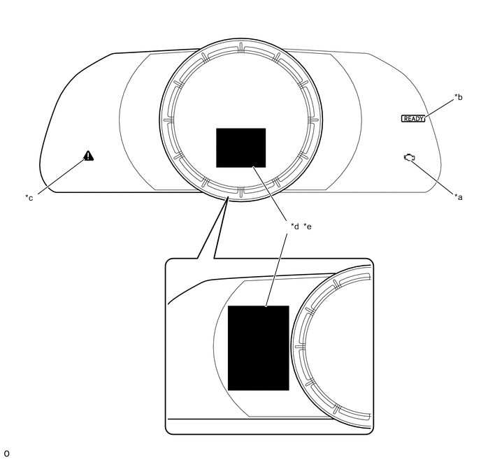
*a MIL *b READY Light *c Master Warning Light *d Charge Warning *e Multi-information Display - - Tech Tips
The master warning light will illuminate when the hybrid control system is malfunctioning and the light will blink when in inspection mode.
-
-
2 TRIP DETECTION LOGIC
-
When a malfunction is first detected, the malfunction is temporarily stored in the hybrid vehicle control ECU assembly memory (1st trip). If the same malfunction is detected during the next drive cycle, the MIL is illuminated (2nd trip).
Following is the description for storage of DTC using "2 trip detection logic".
-
-
FREEZE FRAME DATA
-
The hybrid vehicle control ECU assembly records vehicle and driving condition information as freeze frame data the moment a DTC is stored. When troubleshooting, freeze frame data can be helpful in determining whether the vehicle was moving or stationary, whether the engine was warmed up or not, as well as other data recorded at the time of a malfunction.
-
-
AUXILIARY BATTERY VOLTAGE
-
If voltage is below 11 V, recharge or replace the auxiliary battery.
Note
After turning the power switch off, waiting time may be required before disconnecting the cable from the negative (-) auxiliary battery terminal. Therefore, make sure to read the disconnecting the cable from the negative (-) auxiliary battery terminal notices before proceeding with work.
-
-
MIL (Malfunction Indicator Lamp)
-
The MIL is illuminated when the power switch is first turned on (IG), before the READY light comes on.
-
When the READY indicator turns on, the MIL should turn off. If the MIL remains illuminated, the diagnosis system has detected a malfunction or abnormality in the system.
Tech Tips
If the MIL is not illuminated when the power switch is first turned on (IG), check the MIL circuit.
for SFI System (w/ Canister Pump Module): Click here
for SFI System (w/o Canister Pump Module): Click here
-
-
RELEVANT SYSTEMS CHECK
The inspection areas and outline of the inspection for each circuit are listed below.
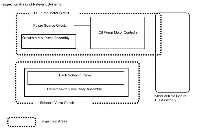
Inspection Details of Relevant Systems System to be Inspected Malfunction Possibility Inspection Content Oil Pump Motor Circuit Oil pump motor lock
-
Open or short in signal line between hybrid vehicle control ECU assembly, oil pump motor controller and oil pump with motor assembly
-
Oil pump motor controller power source circuit
-
Short to +B in oil pump with motor assembly
Solenoid Valve Circuit Solenoid valve inside transmission valve body stuck
-
Check each solenoid valve
-
Check transmission valve body assembly
(no abnormality or foreign matter in solenoid installation area)
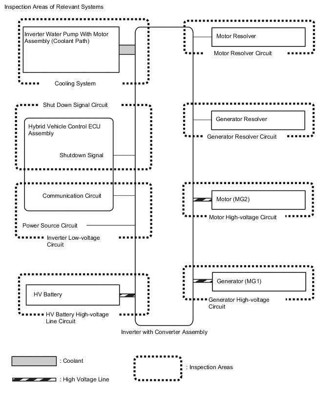
Inspection Details of Relevant Systems System to be Inspected Malfunction Possibility Inspection Content Motor Resolver Circuit Motor resolver signal
-
Open or short circuit in the motor resolver, connectors or cables
Motor High-voltage Circuit Motor (MG2) output
-
Open or short circuit in the motor (MG2), connectors or cables
Generator Resolver Circuit Generator resolver signal
-
Open or short circuit in the generator resolver, connectors or cables
Generator High-voltage Circuit Generator (MG1) output
-
Open or short circuit in the generator (MG1), connectors or cables
Inverter Low-voltage Circuit Power supply voltage from +B or communication between hybrid vehicle control ECU assembly and motor generator control ECU
-
Open or short circuit in communication line between hybrid vehicle control ECU assembly and motor generator control ECU
-
Open or short circuit in the +B or ground lines
-
Fuse is blown
HV Battery High-voltage Line Circuit High voltage power supply from HV battery
-
Open or short circuit in the system main relay, connectors or cables
Cooling System Temperature abnormally high
-
Grille blockage
-
Whether coolant is present
-
Whether there is a possibility that coolant was frozen when malfunction occurs
-
Cooling hose blockage
-
HV radiator fan operation
Shutdown Signal Circuit Shutdown signal
-
Open or short circuit in shutdown signal communication line between hybrid vehicle control ECU assembly and motor generator ECU
-
-
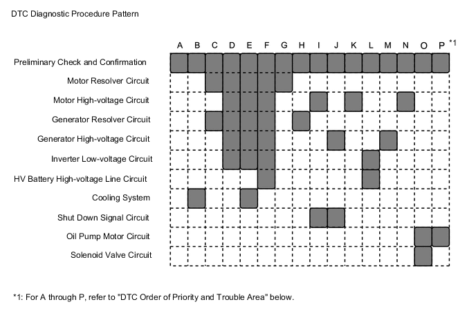
DTC PRIORITY LEVEL AND TROUBLE AREAS
-
Each DTC diagnostic procedure for the hybrid control system consists of a combination of the various relevant system (circuit) inspections.
-
When multiple DTCs are output, performing each diagnostic procedure in order of priority can lead to a more accurate diagnosis.
Inspection Details of Relevant Systems DTC No. Detection Item Order of Priority Inspection Pattern 1 2 3 4 5 Microcomputer Malfunction Power Source Circuit Malfunction Communication System Malfunction Sensor and Actuator Circuit Malfunction System Malfunction P056014 System Voltage (BATT) Circuit Short to Ground or Open - ○ - - - - P060604 Control Module Processor System Internal Failure ○ - - - - - P060647 Hybrid/EV Powertrain Control Module Processor Watchdog / Safety MCU Failure ○ - - - - - P060687 Hybrid/EV Powertrain Control Module Processor to Monitoring Processor Missing Message ○ - - - - - P060694 Control Module Processor Unexpected Operation ○ - - - - - P060A29 Hybrid/EV Powertrain Control Module Monitoring Processor Signal Invalid ○ - - - - - P060A44 Hybrid/EV Powertrain Control Module Monitoring Processor Data Memory Failure ○ - - - - - P060A45 Hybrid/EV Powertrain Control Module Monitoring Processor Program Memory Failure ○ - - - - - P060A47 Hybrid/EV Powertrain Control Module Monitoring Processor Watchdog / Safety MCU Failure ○ - - - - - P060A49 Hybrid/EV Powertrain Control Module Monitoring Processor Internal Electronic Failure ○ - - - - - P060A87 Hybrid/EV Powertrain Control Module Processor from Monitoring Processor Missing Message ○ - - - - - P060A94 Internal Control Module Monitoring Processor Performance Unexpected Operation ○ - - - - - P060B1C Hybrid/EV Powertrain Control Module A/D Processing Voltage Out of Range ○ - - - - - P060B49 Hybrid/EV Powertrain Control Module A/D Processing Internal Electronic Failure ○ - - - - - P060B71 Hybrid/EV Powertrain Control Module A/D Processing Actuator Stuck ○ - - - - - P062F44 Hybrid/EV Powertrain Control Module EEPROM Data Memory Failure ○ - - - - - P06881F ECM/PCM Power Relay Sense Circuit Intermittent - ○ - - - - P071000 Transmission Fluid Temperature Sensor "A" Circuit Range/Performance - - - ○ - - P071011 Transmission Fluid Temperature Sensor "A" Circuit Short To Ground - - - ○ - - P071015 Transmission Fluid Temperature Sensor "A" Circuit Short to Battery or Open - - - ○ - - P072012 Output Speed Sensor Circuit Short to Battery - - - ○ - - P072014 Output Speed Sensor Circuit Short to Ground or Open - - - ○ - - P072031 Output Speed Sensor No Signal - - - ○ - - P074513 Pressure Control Solenoid "A" Circuit Open - - - ○ - - P07457F Pressure Control Solenoid "A" Actuator Stuck Off - - - ○ - O P076A11 Shift Solenoid "H" Control Circuit Short to Ground - - - ○ - - P076A15 Shift Solenoid "H" Control Circuit Short to Battery or Open - - - ○ - - P076A71 Shift Solenoid "H" Control Actuator Stuck - - - ○ - O P077513 Pressure Control Solenoid "B" Circuit Open - - - ○ - - P07757F Pressure Control Solenoid "B" Actuator Stuck Off - - - ○ - O P079513 Pressure Control Solenoid "C" Circuit Open - - - ○ - - P07957F Pressure Control Solenoid "C" Actuator Stuck Off - - - ○ - O P08CC11 Shift Solenoid "J" Control Circuit Short to Ground - - - ○ - - P08CC15 Shift Solenoid "J" Control Circuit Short to Battery or Open - - - ○ - - P08CC71 Shift Solenoid "J" Control Actuator Stuck - - - ○ - O P0A0812 DC/DC Converter Status Circuit Short to Battery - - - ○ - - P0A0814 DC/DC Converter Status Circuit Short to Ground or Open - - - ○ - - P0A0A13 High Voltage System Interlock Circuit Open - - - - ○ - P0A0A92 High Voltage System Interlock Performance or Incorrect Operation - - - - ○ - P0A1112 DC/DC Converter Enable Circuit Short to Battery - - - ○ - - P0A1114 DC/DC Converter Enable Circuit Short to Ground or Open - - - ○ - - P0A1B49 Drive Motor "A" Control Module Internal Electronic Failure ○ - - - - - P0A1B94 Drive Motor "A" Control Module Unexpected Operation ○ - - - - - P0A1F94 Hybrid/EV Battery Energy Control Module Unexpected Operation ○ - - - - - P0A2A11 Drive Motor "A" Temperature Sensor Circuit Short to Ground - - - ○ - - P0A2A15 Drive Motor "A" Temperature Sensor Circuit Short to Auxiliary Battery or Open - - - ○ - - P0A2A1C Drive Motor "A" Temperature Sensor Voltage Out of Range - - - ○ - - P0A2A1F Drive Motor "A" Temperature Sensor Circuit Intermittent - - - ○ - - P0A3611 Generator Temperature Sensor Circuit Short to Ground - - - ○ - - P0A3615 Generator Temperature Sensor Circuit Short to Auxiliary Battery or Open - - - ○ - - P0A361C Generator Temperature Sensor Voltage Out of Range - - - ○ - - P0A361F Generator Temperature Sensor Circuit Intermittent - - - ○ - - P0A9300 Inverter "A" Cooling System Performance - - - - ○ B P0AA000 Hybrid/EV Battery Positive Contactor Circuit Stuck Closed - - - - ○ - P0AA073 Hybrid/EV Battery Positive and Negative Contactor Actuator Stuck Closed - - - - ○ - P0AA373 Hybrid/EV Battery Negative Contactor Actuator Stuck Closed - - - - ○ - P0AA649 Hybrid/EV Battery Voltage System Isolation Internal Electronic Failure - - - - ○ - P0AA749 Hybrid/EV Battery Voltage Isolation Sensor Circuit Internal Electronic Failure - - - ○ - - P0ABF00 Hybrid/EV Battery Current Sensor "A" Circuit Range/Performance - - - ○ - - P0AD911 Hybrid/EV Battery Positive Contactor Circuit Short to Ground - - - ○ - - P0AD915 Hybrid/EV Battery Positive Contactor Circuit Short to Auxiliary Battery or Open - - - ○ - - P0ADD11 Hybrid/EV Battery Negative Contactor Circuit Short to Ground - - - ○ - - P0ADD15 Hybrid/EV Battery Negative Contactor Circuit Short to Auxiliary Battery or Open - - - ○ - - P0AE173 Hybrid/EV Battery Precharge Contactor Actuator Stuck Closed - - - - ○ - P0AE411 Hybrid/EV Battery Precharge Contactor Circuit Short to Ground - - - ○ - - P0AE415 Hybrid/EV Battery Precharge Contactor Circuit Short to Auxiliary Battery or Open - - - ○ - - P0B231C Hybrid/EV Battery "A" Voltage Sensor Voltage Out of Range - - - ○ - - P0C2996 Auxiliary Transmission Fluid Pump Driver Circuit Component Internal Failure - - - ○ - - P0C2B31 Auxiliary Transmission Fluid Pump Control Module Feedback Signal No Signal - - - ○ - - P0C7396 Motor Electronics Coolant Pump "A" Component Internal Failure - - - ○ - - P0C7600 Hybrid/EV Battery System Discharge Time Too Long - - - - ○ - P0D2D1C Drive Motor "A" Inverter Voltage Sensor Voltage Out of Range - - - - ○ - P0E311C Boosting Converter Voltage Sensor "A" Voltage Out of Range - - - - ○ - P160600 Collision detected or Collision Sensor Connection (Open) - - - - - - P160604 Collision detected or Collision Sensor Connection (Open) System Internal Failure - - - - - - P1C2D62 Hybrid/EV Battery "A" Voltage Sensor/Boosting Converter Voltage Sensor "A" Signal Compare Failure - - - - ○ - P1C6A9F Motor Shutdown Stuck Off - - - - ○ - P1C6C9F Generator Shutdown Stuck Off - - - - ○ - P1C7779 Engine Failed to Start Mechanical Linkage Failure - - - ○ - - P1C7C49 Hybrid/EV Battery Voltage System Isolation (A/C Area) Internal Electronic Failure - - - - ○ - P1C7D49 Hybrid/EV Battery Voltage System Isolation (Hybrid/EV Battery Area) Internal Electronic Failure - - - - ○ - P1C7E49 Hybrid/EV Battery Voltage System Isolation (Transaxle Area) Internal Electronic Failure - - - - ○ - P1C7F49 Hybrid/EV Battery Voltage System Isolation (Direct Current Area) Internal Electronic Failure - - - - ○ - P1C8149 High Voltage Power Resource Circuit Consumption Circuit Short - - - - ○ - P1C8249 High Voltage Power Resource Circuit Over Loading - - - - ○ - P1C8349 High Voltage Power Resource Circuit Voltage Sensor after Boosting Malfunction - - - - ○ - P1C8449 High Voltage Power Resource Circuit Short during Ready ON - - - - ○ - P1C8679 Transmission (Input) Mechanical Linkage Failure - - - - ○ - P1C8779 Generator Mechanical Linkage Failure - - - - ○ - P1C8879 Planetary Gear Mechanical Linkage Failure - - - - ○ - P1C9E9F Hybrid/EV System Reset Stuck Off - - - - ○ - P1CCC96 DC/DC Converter Enable Component Internal Failure - - - - ○ - P1CE213 PCU Interlock Circuit Open - - - - ○ - P1CE292 PCU Interlock Performance or Incorrect Operation - - - - ○ - P1CE31C Hybrid/EV Powertrain Control Module Monitoring Processor A/D Processing Voltage Out of Range ○ - - - - - P1CE349 Hybrid/EV Powertrain Control Module Monitoring Processor A/D Processing Internal Electronic Failure ○ - - - - - P1CE371 Hybrid/EV Powertrain Control Module Monitoring Processor A/D Processing Actuator Stuck ○ - - - - - P1CFA12 IGB Signal Circuit Short to Auxiliary Battery ○ - - - - - P212012 Throttle/Pedal Position Sensor/Switch "D" Circuit Short to Auxiliary Battery - - - ○ - - P212014 Throttle/Pedal Position Sensor/Switch "D" Circuit Short to Ground or Open - - - ○ - - P21201C Throttle/Pedal Position Sensor/Switch "D" Voltage Out of Range - - - ○ - - P21201F Throttle/Pedal Position Sensor/Switch "D" Circuit Intermittent - - - ○ - - P212512 Throttle/Pedal Position Sensor/Switch "E" Circuit Short to Auxiliary Battery - - - ○ - - P212514 Throttle/Pedal Position Sensor/Switch "E" Circuit Short to Ground or Open - - - ○ - - P21251C Throttle/Pedal Position Sensor/Switch "E" Voltage Out of Range - - - ○ - - P21251F Throttle/Pedal Position Sensor/Switch "E" Circuit Intermittent - - - ○ - - P213800 Throttle/Pedal Position Sensor/Switch "D"/"E" Voltage Correlation - - - ○ - - P21382B Throttle/Pedal Position Sensor/Switch "D"/"E" Signal Cross Coupled - - - ○ - - P253012 IG2 Signal Circuit Short to Auxiliary Battery ○ - - - - - P271313 Pressure Control Solenoid "D" Circuit Open - - - ○ - - P27137F Pressure Control Solenoid "D" Actuator Stuck Off - - - ○ - O P279762 Auxiliary Transmission Fluid Pump Signal Compare Failure - - - ○ - P P280713 Pressure Control Solenoid "G" Circuit Open - - - ○ - - P28077F Pressure Control Solenoid "G" Actuator Stuck Off - - - ○ - O P300449 High Voltage Power Resource Circuit Short during Pre-Charge - - - - ○ - P310711 Lost Communication with Airbag System Control Module Circuit Short to Ground - - ○ - - - P310715 Lost Communication with Airbag System Control Module Circuit Short to Auxiliary Battery or Open - - ○ - - - P310764 Lost Communication with Airbag System Control Module Signal Plausibility Failure - - ○ - - - P312387 Lost Communication with Drive Motor Control Module "A" from Hybrid/EV Control Module Missing Message - - ○ - - - P314779 Transmission (Shaft) Mechanical Linkage Failure - - - - ○ - P314A31 Motor Electronics Coolant Pump "A" No Signal - - - ○ - - P317511 Oil Pump Motor Temperature Sensor Circuit Short to Ground - - - ○ - - P317515 Oil Pump Motor Temperature Sensor Circuit Short to Auxiliary Battery or Open - - - ○ - - P31B300 Hybrid/EV Battery Voltage High - - - ○ - - P321E9F Motor/Generator Shutdown Signal Stuck Off - - - - ○ - P33B99F Motor/Generator Shutdown Signal (Hybrid/EV Side) Stuck Off - - - - ○ - P33BF9F Motor/Generator Shutdown Signal (MG Side) Stuck Off - - - - ○ - U010087 Lost Communication with ECM/PCM "A" Missing Message - - ○ - - - U011087 Lost Communication with Drive Motor Control Module "A" Missing Message - - ○ - - - U011187 Lost Communication with Hybrid/EV Battery Energy Control Module "A" Missing Message - - ○ - - - U012287 Lost Communication with Vehicle Dynamics Control Module Missing Message - - ○ - - - U012987 Lost Communication with Brake System Control Module Missing Message - - ○ - - - U014087 Lost Communication with Body Control Module Missing Message - - ○ - - - U015187 Lost Communication with Restraints Control Module Missing Message - - ○ - - - U016487 Lost Communication with HVAC Control Module Missing Message - - ○ - - - U029387 Lost Communication with Hybrid/EV Powertrain Control Module Missing Message - - ○ - - - U042481 HVAC Control Module to Hybrid Powertrain Control Module Invalid Serial Data Received - - ○ - - - U110487 Lost Communication with Driving Support ECU Missing Message - - ○ - - - U110787 Lost Communication with Power Management Module Missing Message - - ○ - - - U117087 Lost Communication with Brake System Control Module (Secondary CAN Line) Missing Message - - ○ - - - U117587 Lost Communication with Hybrid/EV Battery Energy Control Module "A" (Powertrain Bus) Missing Message - - ○ - - - U117687 Lost Communication with Gear Shift Control Module "A" (Powertrain Bus) Missing Message - - ○ - - - Tech Tips
The "Example of Multiple DTCs being Output" below is only one example of a malfunction condition. Therefore, a determination should not be made based on this alone.
-
The power supply of the microcomputer decreases while the vehicle is being driven.
-
DTCs are detected and the vehicle behavior is as follows.
- Detected DTCs
-
P060B1C (Hybrid/EV Powertrain Control Module A/D Processing Voltage Out of Range): Microcomputer malfunction*
-
P06881F (ECM/PCM Power Relay Sense Circuit Intermittent): Power source circuit malfunction*
-
P0AA749 (Hybrid/EV Battery Voltage Isolation Sensor Circuit Internal Electronic Failure): Sensor and actuator circuit malfunction*
-
P0B231C (Hybrid/EV Battery "A" Voltage Sensor Voltage Out of Range): Sensor and actuator circuit malfunction*
-
P1C9E9F (Hybrid/EV System Reset Stuck Off): System malfunction*
-
*: Check the priority level in the "DTC Order of Priority" chart above.
- Vehicle Behavior
-
System stopped
-
The inspection order of priority is: Microcomputer circuit → power source circuit → communication circuit → sensor and actuator circuit → system circuit. Therefore, check the repair procedure for P060B1C.
-
Follow the repair procedures and replace the hybrid vehicle control ECU assembly. Finish the repair.
Example of Multiple DTCs being Output:
It is possible to check only the specified malfunctioning parts without having to check irrelevant parts.
-