CAMSHAFT OIL CONTROL VALVE(for Bank 2) INSTALLATION

CAUTION / NOTICE / HINT
CAUTION:
To prevent burns, do not touch the engine, exhaust manifold or other high temperature components while the engine is hot.
PROCEDURE
-
INSTALL CAMSHAFT TIMING GEAR BOLT (for Intake Side of Bank 2)
-
Make sure that the No. 1 cylinder is at TDC/compression.
Tech Tips
Check that the cutout of the camshaft timing gear assembly (for exhaust side) is at the top and align the timing mark (cutout) of the crankshaft pulley with the timing mark on the timing chain cover assembly.
-
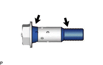
Apply engine oil to the areas of the camshaft timing gear bolt shown in the illustration.
-
While holding the crankshaft pulley, temporarily install the camshaft timing gear bolt.
- Torque:
- 10 N*m { 102 kgf*cm, 7 ft.*lbf }
Note
-
If the camshaft timing gear bolt has been struck or dropped, replace it.
-
If there is any abnormal resistance when temporarily installing the camshaft timing gear bolt, loosen it and make sure that the No. 1 cylinder is at TDC/compression, and then temporarily install the camshaft timing gear bolt again.
Tech Tips
Make sure that the flange part of the camshaft timing gear bolt contacts the entire circumference of the camshaft timing gear assembly.
-
While holding the crankshaft pulley, loosen the camshaft timing gear bolt 60 to 180°.
-
Turn the crankshaft pulley clockwise 30 to 90°.
-

Using SST, hold the crankshaft pulley assembly.
- SST
- 09213-54015 ( 91651-60855 )
- 09330-00021
-
Tighten the camshaft timing gear bolt.
- Torque:
- 95 N*m { 969 kgf*cm, 70 ft.*lbf }
Note
Do not use an impact wrench.
-
-
INSTALL CAMSHAFT TIMING OIL CONTROL SOLENOID ASSEMBLY (for Intake Side of Bank 2)
-
INSTALL CAMSHAFT TIMING GEAR BOLT (for Exhaust Side of Bank 2)
-
Make sure that the No. 1 cylinder is at TDC/compression.
Tech Tips
Check that the cutout of the camshaft timing gear assembly (for exhaust side) is at the top and align the timing mark (cutout) of the crankshaft pulley with the timing mark on the timing chain cover assembly.
-
Apply engine oil to the areas of the camshaft timing gear bolt shown in the illustration.
-
While holding the crankshaft pulley, temporarily install the camshaft timing gear bolt.
- Torque:
- 10 N*m { 102 kgf*cm, 7 ft.*lbf }
Note
-
If the camshaft timing gear bolt has been struck or dropped, replace it.
-
If there is any abnormal resistance when temporarily installing the camshaft timing gear bolt, loosen it and make sure that the No. 1 cylinder is at TDC/compression, and then temporarily install the camshaft timing gear bolt again.
Tech Tips
Make sure that the flange part of the camshaft timing gear bolt contacts the entire circumference of the camshaft timing gear assembly.
-
Using SST, hold the crankshaft pulley assembly.
- SST
- 09213-54015 ( 91651-60855 )
- 09330-00021
-
Tighten the camshaft timing gear bolt.
- Torque:
- 95 N*m { 969 kgf*cm, 70 ft.*lbf }
Note
Do not use an impact wrench.
-
-
INSTALL CAMSHAFT TIMING OIL CONTROL SOLENOID ASSEMBLY (for Exhaust Side of Bank 2)
-
INSTALL LOWER RADIATOR AIR DEFLECTOR
-
INSTALL RADIATOR SUPPORT TO FRAME SEAL RH
-
INSTALL V-BANK COVER SUB-ASSEMBLY