CAMSHAFT OIL CONTROL VALVE(for Bank 2) REMOVAL

PROCEDURE
-
REMOVE V-BANK COVER SUB-ASSEMBLY
-
REMOVE RADIATOR SUPPORT TO FRAME SEAL RH
-
REMOVE LOWER RADIATOR AIR DEFLECTOR
-
REMOVE CAMSHAFT TIMING OIL CONTROL SOLENOID ASSEMBLY (for Exhaust Side of Bank 2)
-
REMOVE CAMSHAFT TIMING OIL CONTROL SOLENOID ASSEMBLY (for Intake Side of Bank 2)
-
SET NO. 1 CYLINDER TO TDC/COMPRESSION
-
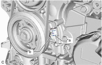
*a Timing Mark *b Timing Mark (Cutout) Turn the crankshaft pulley clockwise until its timing mark (cutout) is aligned with the timing mark on the timing chain cover assembly as shown in the illustration.
-

*a Correct *b Incorrect *c Cutout *d Up Check that the cutout of the camshaft timing gear assembly (for exhaust side) is at the top.
Tech Tips
-
If the cutout of the camshaft timing gear assembly (for exhaust side) is not at the top, turn the crankshaft 360° clockwise and align the timing mark (cutout) of the crankshaft pulley with the timing mark on the timing chain cover assembly again.
-
As there are no cutouts on the camshaft timing gear (for intake side), check the position of the cutout of the camshaft timing gear (for exhaust side) to confirm that the No. 1 cylinder is at TDC/compression.
-
-
-
REMOVE CAMSHAFT TIMING GEAR BOLT (for Exhaust Side of Bank 2)
-

Using SST, hold the crankshaft pulley assembly.
- SST
- 09213-54015 ( 91651-60855 )
- 09330-00021
-

Remove the camshaft timing gear bolt.
Note
-
If the camshaft timing gear bolt has been struck or dropped, replace it.
-
Do not turn the crankshaft pulley after removing the camshaft timing gear bolt.
-
-
-
REMOVE CAMSHAFT TIMING GEAR BOLT (for Intake Side of Bank 2)
-
Using SST, hold the crankshaft pulley assembly.
- SST
- 09213-54015 ( 91651-60855 )
- 09330-00021
-
Remove the camshaft timing gear bolt.
Note
-
If the camshaft timing gear bolt has been struck or dropped, replace it.
-
Do not turn the crankshaft pulley after removing the camshaft timing gear bolt.
-
-