SFI SYSTEM(w/o Canister Pump Module), Diagnostic DTC:P03352A, P033531
| DTC Code | DTC Name |
|---|---|
| P03352A | Crankshaft Position Sensor "A" Signal Stuck in Range |
| P033531 | Crankshaft Position Sensor "A" No Signal |
DESCRIPTION
Refer to DTC P033511.
| DTC No. | Detection Item | DTC Detection Condition | Trouble Area | MIL | Memory | Note |
|---|---|---|---|---|---|---|
| P03352A | Crankshaft Position Sensor "A" Signal Stuck in Range | No crankshaft position sensor signal to the ECM while cranking (1 trip detection logic). |
|
Comes on | DTC stored | SAE: P0335 |
| P033531 | Crankshaft Position Sensor "A" No Signal | The engine stalls and the engine speed signal value decreases rapidly (1 trip detection logic). |
|
Comes on | DTC stored | SAE: P0335 |
-
Reference: Inspection using an oscilloscope.
MONITOR DESCRIPTION
A DTC will be stored if any of the following occurs:
-
The crankshaft position sensor signal (NE signal) is not received by the ECM when the engine is being cranked.
-
The engine stalls and the engine speed signal value decreases rapidly (under normal conditions the engine speed will decrease gradually).
MONITOR STRATEGY
| Required Sensors/Components (Main) | Crankshaft position sensor |
| Required Sensors/Components (Related) | VVT sensor |
| Frequency of Operation | Continuous |
CONFIRMATION DRIVING PATTERN
-
Connect the GTS to the DLC3.
-
Turn the power switch on (IG).
-
Turn the GTS on.
-
Clear the DTCs (even if no DTCs are stored, perform the clear DTC procedure).
-
Turn the power switch off and wait for at least 30 seconds.
-
Turn the power switch on (IG).
-
Turn the GTS on.
-
Put the engine in Inspection Mode (2WD for measuring Exhaust Gas).
-
Start the engine.
-
Idle the engine for 20 seconds or more [A].
-
Enter the following menus: Powertrain / Engine / Trouble Codes [B].
-
Read the pending DTCs.
Tech Tips
-
If a pending DTC is output, the system is malfunctioning.
-
If a pending DTC is not output, perform the following procedure.
-
-
Enter the following menus: Powertrain / Engine / Utility / All Readiness.
-
Input the DTC: P03352A or P033531.
-
Check the DTC judgment result.
GTS Display Description NORMAL
-
DTC judgment completed
-
System normal
ABNORMAL
-
DTC judgment completed
-
System abnormal
INCOMPLETE
-
DTC judgment not completed
-
Perform driving pattern after confirming DTC enabling conditions
Tech Tips
-
If the judgment result shows NORMAL, the system is normal.
-
If the judgment result shows ABNORMAL, the system has a malfunction.
-
If the judgment result shows INCOMPLETE, perform steps [A] and [B] again.
-
CAUTION / NOTICE / HINT
Note
-
Vehicle Control History may be stored in the hybrid vehicle control ECU if the engine is malfunctioning. Certain vehicle condition information is recorded when Vehicle Control History is stored. Reading the vehicle conditions recorded in both the freeze frame data and Vehicle Control History can be useful for troubleshooting.
(Select Powertrain in Health Check and then check the time stamp data.)
-
If any "Engine Malfunction" Vehicle Control History item has been stored in the hybrid vehicle control ECU, make sure to clear it. However, as all Vehicle Control History items are cleared simultaneously, if any Vehicle Control History items other than "Engine Malfunction" are stored, make sure to perform any troubleshooting for them before clearing Vehicle Control History.
Tech Tips
-
If no problem is found by this diagnostic troubleshooting procedure, check for problems by referring to the engine mechanical section.
-
The engine speed can be checked by using the GTS. To perform the check, follow the procedures below:
-
Connect the GTS to the DLC3.
-
Turn the power switch on (IG).
-
Turn the GTS on.
-
Put the engine in Inspection Mode (2WD for measuring Exhaust Gas).
-
Start the engine.
-
Enter the following menus: Powertrain / Engine / Data List / Engine Speed.
-
The engine speed may be indicated as zero despite the engine running normally. This is caused by a lack of NE signals from the crankshaft position sensor. Alternatively, the engine speed may be indicated as lower than the actual engine speed if the crankshaft position sensor output voltage is insufficient.
-
Read freeze frame data using the GTS. The ECM records vehicle and driving condition information as freeze frame data the moment a DTC is stored. When troubleshooting, freeze frame data can help determine if the vehicle was moving or stationary, if the engine was warmed up or not, if the air fuel ratio was lean or rich, and other data from the time the malfunction occurred.
PROCEDURE
-
READ VALUE USING GTS (ENGINE SPEED)
-
Connect the GTS to the DLC3.
-
Turn the power switch on (IG).
-
Turn the GTS on.
-
Put the engine in Inspection Mode (2WD for measuring Exhaust Gas).
Powertrain > Hybrid Control > UtilityTester Display Inspection Mode -
Enter the following menus: Powertrain / Engine / Data List / Engine Speed.
Powertrain > Engine > Data ListTester Display Engine Speed -
Start the engine.
-
Read the values displayed on the GTS while the engine is running.
Standard Correct values are displayed. Tech Tips
-
To check the engine speed change, display the graph on the GTS.
-
If the engine does not start, check the engine speed while cranking.
-
If the engine speed indicated on the GTS remains at zero (0), there may be an open or short in the crankshaft position sensor circuit.
Result Proceed to OK NG -
OK 
CHECK FOR INTERMITTENT PROBLEMS Click here
NG 
-
-
CHECK HARNESS AND CONNECTOR
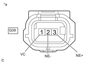
*a Front view of wire harness connector
(to Crankshaft Position Sensor)
Tech Tips
Make sure that the connector is properly connected. If it is not, securely connect it and check for DTCs again.
-
Disconnect the crankshaft position sensor connector.
-
Turn the power switch on (IG).
-
Measure the voltage according to the value(s) in the table below.
Standard Voltage Tester Connection Condition Specified Condition G39-1 (VC) - Body ground Power switch on (IG) 4.5 to 5.5 V G39-3 (NE+) - Body ground Power switch on (IG) 3.0 to 5.5 V -
Turn the power switch off and wait for at least 30 seconds.
-
Measure the resistance according to the value(s) in the table below.
Standard Resistance Tester Connection Condition Specified Condition G39-1 (VC) - G39-3 (NE+) Power switch off 1.425 to 1.575 kΩ G39-2 (NE-) - Body ground Always Below 1 Ω Result Proceed to OK NG
NG 
CHECK HARNESS AND CONNECTOR (CRANKSHAFT POSITION SENSOR - ECM) Click here
OK
-
-
CHECK SENSOR INSTALLATION AND CONDUCT VISUAL INSPECTION (CRANKSHAFT POSITION SENSOR)
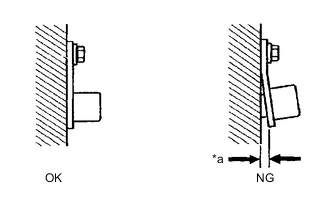
*a Clearance
-
Visually check the crankshaft position sensor for damage.
-
Check the crankshaft position sensor installation condition.
OK The crankshaft position sensor does not have any damage and is installed properly. Result Proceed to OK NG
NG
REPLACE OR SECURELY REINSTALL CRANKSHAFT POSITION SENSOR
OK
-
-
INSPECT FLYWHEEL SUB-ASSEMBLY (TEETH OF SENSOR PLATE)
-
Inspect the teeth of the crankshaft angle sensor plate.
OK Crankshaft angle sensor plate does not have any cracks or deformation. Result Proceed to OK NG
OK
REPLACE CRANKSHAFT POSITION SENSOR Click here
NG
REPLACE FLYWHEEL SUB-ASSEMBLY Click here
-
-
CHECK HARNESS AND CONNECTOR (CRANKSHAFT POSITION SENSOR - ECM)
-
Disconnect the crankshaft position sensor connector.
-
Disconnect the ECM connector.
-
Measure the resistance according to the value(s) in the table below.
Standard Resistance Tester Connection Condition Specified Condition G39-3 (NE+) - G1-128 (NE+) Always Below 1 Ω G39-2 (NE-) - G1-95 (NE-) Always Below 1 Ω G39-1 (VC) - G1-96 (VCNE) Always Below 1 Ω G39-3 (NE+) or G1-128 (NE+) - Body ground and other terminals Always 10 kΩ or higher G39-2 (NE-) or G1-95 (NE-) - Body ground and other terminals Always 10 kΩ or higher G39-1 (VC) or G1-96 (VCNE) - Body ground and other terminals Always 10 kΩ or higher Result Proceed to OK NG
OK
REPLACE ECM Click here
NG
REPAIR OR REPLACE HARNESS OR CONNECTOR
-