SFI SYSTEM(w/o Canister Pump Module), Diagnostic DTC:P020113, P020213, P020313, P020413, P020513, P020613, P062D13
| DTC Code | DTC Name |
|---|---|
| P020113 | Cylinder 1 Injector "A" Circuit Open |
| P020213 | Cylinder 2 Injector "A" Circuit Open |
| P020313 | Cylinder 3 Injector "A" Circuit Open |
| P020413 | Cylinder 4 Injector "A" Circuit Open |
| P020513 | Cylinder 5 Injector "A" Circuit Open |
| P020613 | Cylinder 6 Injector "A" Circuit Open |
| P062D13 | Fuel Injector Driver Circuit Performance Bank 1 Circuit Open |
DESCRIPTION
The D-4S system has two fuel injection systems. One is an in-cylinder direct injection system that directly injects pressurized fuel into the combustion chamber. The other is an intake port injection system. The ECM determines which fuel injection system to use in accordance with the engine conditions. The direct injection system uses an injector driver (EDU) built into the ECM to rapidly operate the direct fuel injector assemblies. It converts injection request signals from the ECM to high-voltage and high-current injector-drive signals that drive the fuel injector assemblies (for direct injection).
| DTC No. | Detection Item | DTC Detection Condition | Trouble Area | MIL | Memory | Note |
|---|---|---|---|---|---|---|
| P020113 | Cylinder 1 Injector "A" Circuit Open | One of following conditions is met (1 trip detection logic):
|
|
Comes on | DTC stored | SAE: P0201 |
| P020213 | Cylinder 2 Injector "A" Circuit Open | One of following conditions is met (1 trip detection logic):
|
|
Comes on | DTC stored | SAE: P0202 |
| P020313 | Cylinder 3 Injector "A" Circuit Open | One of following conditions is met (1 trip detection logic):
|
|
Comes on | DTC stored | SAE: P0203 |
| P020413 | Cylinder 4 Injector "A" Circuit Open | One of following conditions is met (1 trip detection logic):
|
|
Comes on | DTC stored | SAE: P0204 |
| P020513 | Cylinder 5 Injector "A" Circuit Open | One of following conditions is met (1 trip detection logic):
|
|
Comes on | DTC stored | SAE: P0205 |
| P020613 | Cylinder 6 Injector "A" Circuit Open | One of following conditions is met (1 trip detection logic):
|
|
Comes on | DTC stored | SAE: P0206 |
| P062D13 | Fuel Injector Driver Circuit Performance Bank 1 Circuit Open | Open or short in all fuel injector assembly (for direct injection) circuits for 60 times or more (1 trip detection logic). |
|
Comes on | DTC stored | SAE: P062D |
MONITOR DESCRIPTION
The fuel injection sequence occurs in numerical order from No. 1 to No. 6.
The ECM monitors the Injector Driver (EDU) at all times. If drivers or fuel injector assembly (for direct injection) is malfunctioning, the EDU sends fuel injector assembly (for direct injection) operation condition signals (fail signals) to the ECM. When the ECM receives the signals, the ECM stops the fuel injection control of the appropriate cylinders, cuts voltage to the appropriate EDU relay, and illuminates the MIL.
MONITOR STRATEGY
| Required Sensors/Components | Fuel injector assembly (for direct injection) ECM (injector driver) |
| Frequency of Operation | Continuous |
CONFIRMATION DRIVING PATTERN
-
Connect the GTS to the DLC3.
-
Turn the power switch on (IG) and turn the GTS on.
-
Clear the DTCs (even if no DTCs are stored, perform the clear DTC procedure).
-
Turn the power switch off and wait for at least 30 seconds.
-
Turn the power switch on (IG) and turn the GTS on.
-
Put the engine in Inspection Mode (2WD for measuring Exhaust Gas).
-
Start the engine and warm it up.
-
Idle the engine for 15 seconds or more [A].
-
Enter the following menus: Powertrain / Engine / Trouble Codes / Pending [B].
-
Read pending DTCs.
Tech Tips
-
If a pending DTC is output, the system is malfunctioning.
-
If a pending DTC is not output, perform the following procedure.
-
-
Enter the following menus: Powertrain / Engine / Utility / All Readiness.
-
Input the DTC: P020113, P020213, P020313, P020413, P020513, P020613 or P062D13.
-
Check the DTC judgment result.
GTS Display Description NORMAL
-
DTC judgment completed
-
System normal
ABNORMAL
-
DTC judgment completed
-
System abnormal
INCOMPLETE
-
DTC judgment not completed
-
Perform driving pattern after confirming DTC enabling conditions
Tech Tips
-
If the judgment result shows NORMAL, the system is normal.
-
If the judgment result shows ABNORMAL, the system has a malfunction.
-
If the judgment result shows INCOMPLETE, perform steps [A] and [B] again.
-
WIRING DIAGRAM
CAUTION / NOTICE / HINT
Note
-
Inspect the fuses for circuits related to this system before performing the following procedure.
-
Vehicle Control History may be stored in the hybrid vehicle control ECU if the engine is malfunctioning. Certain vehicle condition information is recorded when Vehicle Control History is stored. Reading the vehicle conditions recorded in both the freeze frame data and Vehicle Control History can be useful for troubleshooting.
(Select Powertrain in Health Check and then check the time stamp data.)
-
If any "Engine Malfunction" Vehicle Control History item has been stored in the hybrid vehicle control ECU, make sure to clear it. However, as all Vehicle Control History items are cleared simultaneously, if any Vehicle Control History items other than "Engine Malfunction" are stored, make sure to perform any troubleshooting for them before clearing Vehicle Control History.
Tech Tips
-
If the current from the EDU relay is cut because DTC P062D13 is stored, DTC P123513 will be stored even if the fuel pump assembly (for high pressure side) is normal.
-
Read freeze frame data using the GTS. The ECM records vehicle and driving condition information as freeze frame data the moment a DTC is stored. When troubleshooting, freeze frame data can help determine if the vehicle was moving or stationary, if the engine was warmed up or not, if the air fuel ratio was lean or rich, and other data from the time the malfunction occurred.
PROCEDURE
-
CHECK DTC OUTPUT (DTC P020113, P020213, P020313, P020413 AND/OR P062D13)
-
Connect the GTS to the DLC3.
-
Turn the power switch on (IG).
-
Turn the GTS on.
-
Enter the following menus: Powertrain / Engine / Trouble Codes.
-
Read the DTCs.
Powertrain > Engine > Trouble CodesResult Result Proceed to DTC P020113, P020213, P020313, P020413, P020513 or P020613 is output A 3 or more of the following DTCs are output: P062D13, P020113, P020213, P020313, P020413, P020513 or P020613 B P062D13 is output
B 
INSPECT EDU RELAY Click here
A 
-
-
CHECK HARNESS AND CONNECTOR
-
Disconnect the ECM connector.
-
Measure the resistance according to the value(s) in the table below.
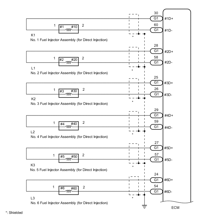
Standard Resistance Tester Connection Condition Specified Condition G1-30 (#1D+) - G1-60 (#1D-) 20°C (68°F) 1.74 to 2.04 Ω G1-28 (#2D+) - G1-58 (#2D-) 20°C (68°F) 1.74 to 2.04 Ω G1-25 (#3D+) - G1-26 (#3D-) 20°C (68°F) 1.74 to 2.04 Ω G1-29 (#4D+) - G1-59 (#4D-) 20°C (68°F) 1.74 to 2.04 Ω G1-27 (#5D+) - G1-57 (#5D-) 20°C (68°F) 1.74 to 2.04 Ω G1-24 (#6D+) - G1-54 (#6D-) 20°C (68°F) 1.74 to 2.04 Ω G1-30 (#1D+) or G1-60 (#1D-) - Body ground and other terminals Always 1 MΩ or higher G1-28 (#2D+) or G1-58 (#2D-) - Body ground and other terminals Always 1 MΩ or higher G1-25 (#3D+) or G1-26 (#3D-) - Body ground and other terminals Always 1 MΩ or higher G1-29 (#4D+) or G1-59 (#4D-) - Body ground and other terminals Always 1 MΩ or higher G1-27 (#5D+) or G1-57 (#5D-) - Body ground and other terminals Always 1 MΩ or higher G1-24 (#6D+) or G1-54 (#6D-) - Body ground and other terminals Always 1 MΩ or higher Tech Tips
The standard values shown are fuel injector assembly (for direct injection) resistance values.
Result Proceed to OK NG
OK 
REPLACE ECM Click here
NG
-
-
INSPECT FUEL INJECTOR ASSEMBLY (FOR DIRECT INJECTION (RESISTANCE))
-
Check the resistance of the fuel injector assembly (for direct injection).
Tech Tips
Perform "Inspection After Repair" after replacing the fuel injector assembly (for direct injection).
Result Proceed to OK NG
OK
REPAIR OR REPLACE HARNESS OR CONNECTOR (FUEL INJECTOR ASSEMBLY (FOR DIRECT INJECTION) - ECM)
NG
REPLACE FUEL INJECTOR ASSEMBLY (FOR DIRECT INJECTION) Click here
-
-
INSPECT EDU RELAY
-
Inspect the EDU relay.
Result Proceed to OK NG
NG
REPLACE EDU RELAY
OK
-
-
CHECK HARNESS AND CONNECTOR (AUXILIARY BATTERY - EDU RELAY)
-
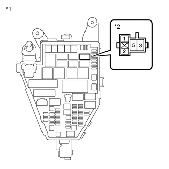
*1 No. 1 Engine Room Relay Block and Junction Block Assembly *2 EDU Relay Remove the EDU relay from the No. 1 engine room relay block and junction block assembly.
-
Measure the voltage according to the value(s) in the table below.
Standard Voltage Tester Connection Condition Specified Condition 5 (EDU relay) - Body ground Always 11 to 14 V Result Proceed to OK NG
NG
REPAIR OR REPLACE HARNESS OR CONNECTOR (AUXILIARY BATTERY - EDU RELAY)
OK
-
-
CHECK HARNESS AND CONNECTOR (EDU RELAY - ECM)
-
Remove the EDU relay from the No. 1 engine room relay block and junction block assembly.
-
Disconnect the ECM connector.
-
Measure the resistance according to the value(s) in the table below.
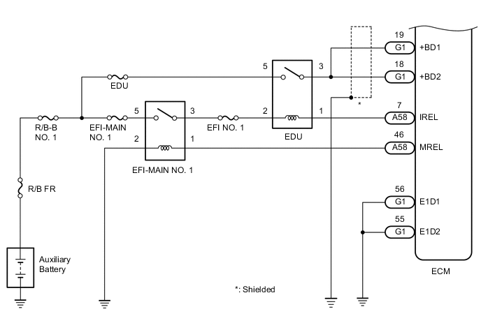
Standard Resistance Tester Connection Condition Specified Condition 3 (EDU relay) - G1-19 (+BD1) Always Below 1 Ω 3 (EDU relay) - G1-18 (+BD2) Always Below 1 Ω 3 (EDU relay) or G1-19 (+BD1) - Body ground and other terminals Always 10 kΩ or higher 3 (EDU relay) or G1-18 (+BD2) - Body ground and other terminals Always 10 kΩ or higher Result Proceed to OK NG
NG
REPAIR OR REPLACE HARNESS OR CONNECTOR
OK
-
-
CHECK HARNESS AND CONNECTOR (EFI-MAIN NO. 1 RELAY - EDU RELAY)
-
Remove the EFI-MAIN NO. 1 relay, EDU relay and A/F HTR relay from the No. 1 engine room relay block and junction block assembly.
-
Remove the EFI-MAIN NO. 2 relay from the No. 2 luggage room relay block and junction block assembly.
Tech Tips
Remove the EFI-MAIN No. 2 relay and A/F HTR relay connected between the checked terminals as the coil inside the relay influences the measurement value.
-
Measure the resistance according to the value(s) in the table below.
Standard Resistance Tester Connection Condition Specified Condition 3 (EFI-MAIN NO. 1 relay) - 2 (EDU relay) Always Below 1 Ω 3 (EFI-MAIN NO. 1 relay) or 2 (EDU relay) - Body ground and other terminals Always 10 kΩ or higher Result Proceed to OK NG
NG
REPAIR OR REPLACE HARNESS OR CONNECTOR
OK
-
-
CHECK HARNESS AND CONNECTOR (EDU RELAY - ECM)
-
Remove the EDU relay from the No. 1 engine room relay block and junction block assembly.
-
Disconnect the ECM connector.
-
Measure the resistance according to the value(s) in the table below.
Standard Resistance Tester Connection Condition Specified Condition 1 (EDU relay) - A58-7 (IREL) Always Below 1 Ω 1 (EDU relay) or A58-7 (IREL) - Body ground and other terminals Always 10 kΩ or higher Result Proceed to OK NG
OK
REPLACE ECM Click here
NG
REPAIR OR REPLACE HARNESS OR CONNECTOR
-