SFI SYSTEM(w/ Canister Pump Module) EVAP System
RELATED DTCS
| DTC No. | SAE | Monitoring Item | Link |
|---|---|---|---|
| P043E00 | P043E | Reference orifice low flow | |
| P043F00 | P043F | Reference orifice high flow | |
| P04417E | P0441 | Purge VSV stuck open | |
| P04417F | P0441 | Purge VSV stuck closed | |
| P04419C | P0441 | Insufficient purge flow | |
| P045011 | P0452 | Canister pressure sensor (built into canister pump module) voltage low | |
| P045015 | P0453 | Canister pressure sensor (built into canister pump module) voltage high | |
| P04502F | P0451 | Canister pressure sensor (built into canister pump module) signal noise | |
| P142000 | P1420 | Small or 0.02 inch leak from canister | |
| P142100 | P1421 | Gross leak from canister | |
| P142200 | P1422 | Small or 0.02 inch leak from fuel tank | |
| P142300 | P1423 | Gross leak from fuel tank | |
| P145011 | P1452 | Fuel tank pressure sensor voltage low | |
| P145015 | P1453 | Fuel tank pressure sensor voltage high | |
| P14502A | P1451 | Fuel tank pressure sensor signal noise | |
| P14502F | P1451 | Fuel tank pressure sensor signal fixed/flat | |
| P24007E | P2402 | Leak detection pump (built into canister pump module) stuck on | |
| P24007F | P2401 | Leak detection pump (built into canister pump module) stuck off | |
| P24187E | P2419 | Vent valve (built into canister pump module) stuck closed | |
| P24187F | P2420 | Vent valve (built into canister pump module) stuck open (vent) | |
| P24507E | P2450 | Fuel vapor-containment valve stuck open | |
| P24517F | P2451 | Fuel vapor-containment valve stuck closed | |
| P261029 | P2610 | Soak timer (built into ECM) | |
| P261093 | P2610 |
DESCRIPTION
While the engine is running, if predetermined conditions (closed loop, etc.) are met, the purge VSV is opened by the ECM and stored fuel vapors in the canister are purged to the intake manifold. The ECM will change the duty cycle ratio of the purge VSV to control purge flow volume.
Purge flow volume is also determined by the intake manifold pressure. Atmospheric pressure is allowed to enter the canister through the vent valve to ensure that purge flow is maintained when negative pressure (vacuum) is applied to the canister.
The ECM monitors the condition of both the key-off monitor and purge flow monitor to ensure proper operation of the EVAP system.
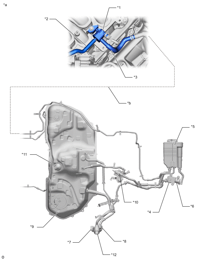
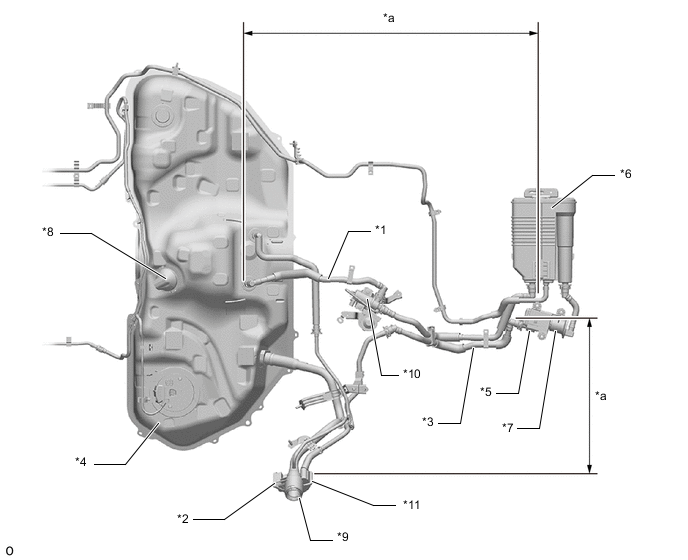
| *1 | Purge VSV | *2 | Fuel Vapor Feed Hose Assembly (EVAP Hose) (to Intake Air Surge Tank Assembly) |
| *3 | Fuel Vapor Feed Hose Assembly (EVAP Hose) (from Canister) | *4 | Canister Pump Module - Canister Pressure Sensor - Leak Detection Pump - Vent Valve |
| *5 | Canister | *6 | Trap Canister |
| *7 | Air Inlet Port | *8 | Canister Filter |
| *9 | Fuel Tank Assembly | *10 | Fuel Vapor-containment Valve |
| *11 | Fuel Tank Pressure Sensor | *12 | Fuel Tank Cap Assembly |
| *a | Location of EVAP (Evaporative Emission) System | *b | Purge Line |
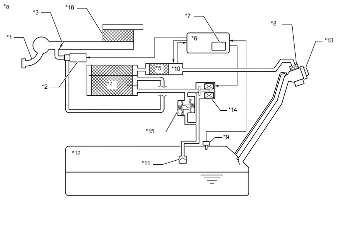
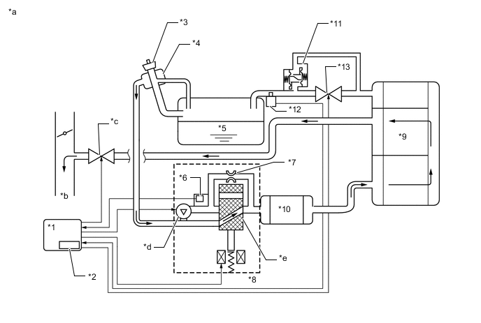
| *1 | Intake Manifold | *2 | Purge VSV |
| *3 | Throttle Valve | *4 | Canister |
| *5 | Trap Canister | *6 | ECM |
| *7 | Soak Timer | *8 | Canister Filter |
| *9 | Fuel Tank Pressure Sensor | *10 | Canister Pump Module - Canister Pressure Sensor - Leak Detection Pump - Vent Valve |
| *11 | Cut-off Valve | *12 | Fuel Tank Assembly |
| *13 | Fuel Tank Cap Assembly | *14 | Fuel Vapor-containment Valve |
| *15 | Fuel Outlet Valve (Relief Valve) | *16 | Air Cleaner |
| *a | EVAP System Circuit | - | - |
| Component | Operation |
|---|---|
| Canister | Contains activated charcoal to absorb EVAP (Evaporative Emissions) generated in fuel tank. |
| Trap Canister | Contains activated charcoal to absorb EVAP generated in fuel tank. |
| Cut-off valve | Located in the fuel tank. Valve closes by its own weight when vehicle is overturned to prevent fuel from spilling out. |
| Purge VSV (Vacuum Switching Valve) | Opens or closes line between canister and intake manifold. ECM uses purge VSV to control EVAP purge flow. In order to discharge EVAP absorbed by canister to intake manifold, ECM opens purge VSV. EVAP discharge volume to intake manifold controlled by purge VSV duty cycle (current-carrying time). (Open: on, Close: off) |
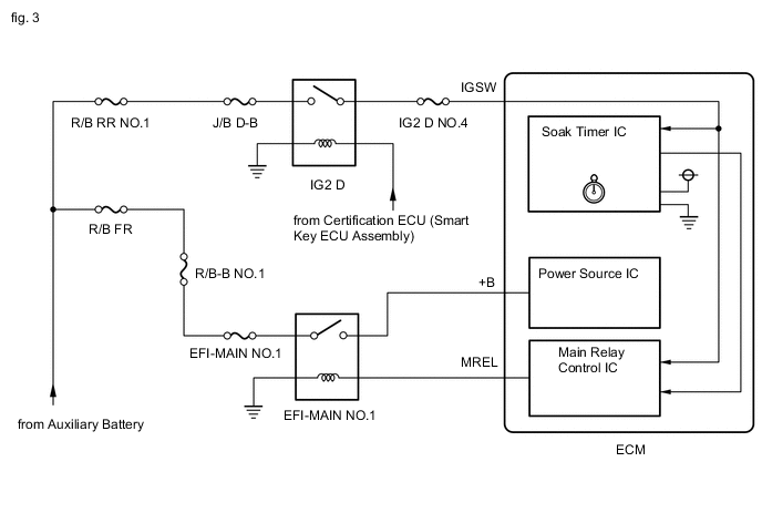
| Soak timer | Built into ECM. To ensure accurate EVAP monitor, measures 5 hours (+/-15 min) after power switch is turned off. This allows fuel to cool down, stabilizing EVAP pressure. When approximately 5 hours elapsed, ECM activates (refer to fig. 3). |
| Fuel vapor-containment valve | Opens and closes line between fuel tank and canister. When vehicle is stopped, this valve stays closed to keep fuel vapors in the tank and prevent them from being absorbed by canister. During refueling, valve opens to allow fuel vapors from tank to be absorbed by canister. When the vehicle is being driven, the valve maintains a slight positive pressure in the fuel tank. |
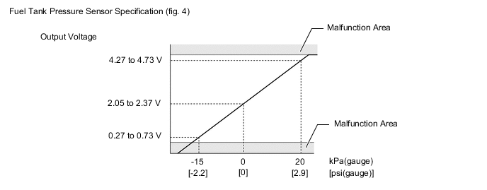
| Fuel tank pressure sensor | Converts pressure in fuel tank into voltage reading for use by ECM. ECM supplies 5 V to sensor, and uses voltage reading that is output as feedback to allow monitoring of fuel tank pressure (refer to fig. 4). |
| Canister pump module | Consists of (a) to (d) below. Canister pump module cannot be disassembled. |
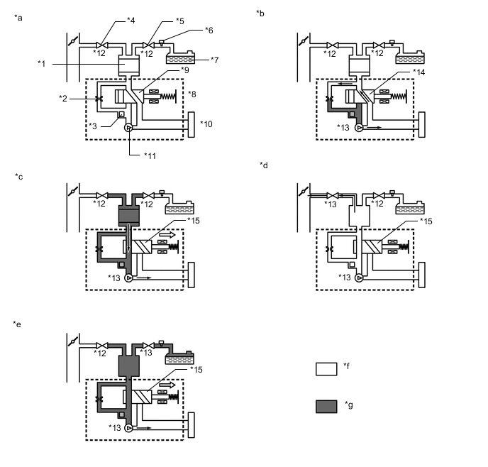
| (a) Vent valve | Vents and closes EVAP system. When ECM turns valve on, EVAP system is closed. When ECM turns valve off, EVAP system is vented. Negative pressure (vacuum) is created in EVAP system to check for EVAP leaks by closing purge VSV, turning on vent valve (closing it) and operating leak detection pump (refer to fig. 1). |
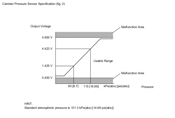
| (b) Canister pressure sensor | Indicates pressure as voltages. ECM supplies regulated 5 V to pressure sensor, and uses feedback from sensor to monitor EVAP system pressure (refer to fig. 2). |
| (c) Leak detection pump | Creates negative pressure (vacuum) in EVAP system for leak check. |
| (d) Reference orifice | Has opening with 0.02 inch diameter. Vacuum is produced through orifice by closing purge VSV, turning off vent valve and operating leak detection pump, to monitor reference pressure. Reference pressure is used when checking for small EVAP leaks. |
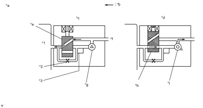
| *1 | Canister | *2 | Reference Orifice (0.02 Inch) |
| *3 | Canister Pressure Sensor | - | - |
| *a | Canister Pump Module (fig. 1) | *b | Airflow |
| *c | Condition: Purge Flow | *d | Condition: Leak Check |
| *e | Vent Valve: off (vent) | *f | to Canister Filter (Atmosphere) |
| *g | Leak Detection Pump: off | *h | Vent Valve: on (closed) |
| *i | Leak Detection Pump: on | - | - |
-
Key-off monitor
This monitor checks for EVAP (evaporative emission) system leaks and canister pump module malfunctions. The monitor starts 5 hours* after the power switch is turned off. At least 5 hours are required for the fuel to cool down to stabilize the EVAP pressure, thus making the EVAP system monitor more accurate.
The leak detection pump creates negative pressure (vacuum) in the EVAP system and the pressure is measured. Finally, the ECM monitors for leaks from the EVAP system, and malfunctions in both the canister pump module and purge VSV based on the EVAP pressure.
Tech Tips
*: If the engine coolant temperature is not less than 35°C (95°F) 5 hours after the power switch is turned off, the monitor check starts 2 hours later. If it is still not less than 35°C (95°F) 7 hours after the power switch is turned off, the monitor check starts 2.5 hours later.
-
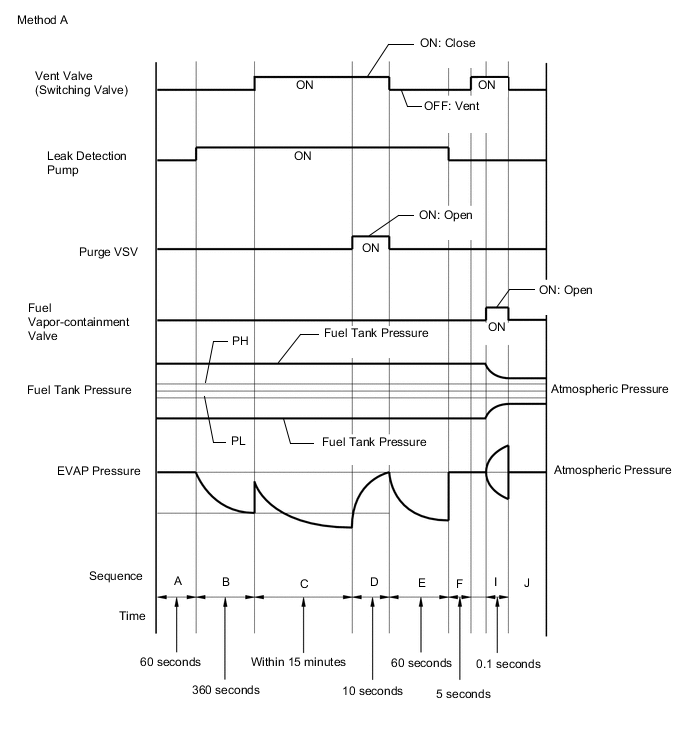
If the fuel tank pressure is higher or lower than the atmospheric pressure, the system determines that there are no leaks in the closed tank system and the system will check for leaks from the piping and canister between the purge VSV and canister pump module. (Method A)
-
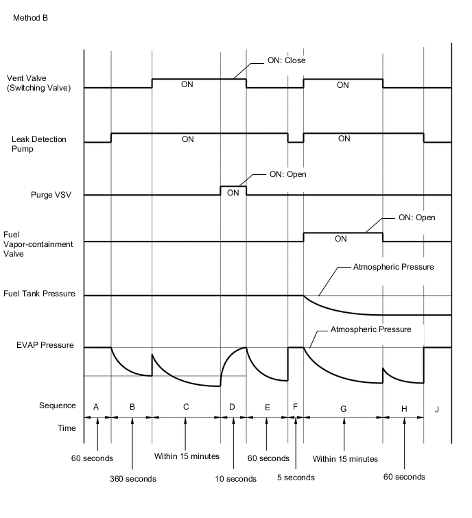
If the fuel tank pressure is almost the same as the atmospheric pressure, vacuum will be allowed to enter the fuel tank and the system will check for leaks from the fuel tank after checking for leaks from the canister. (Method B)
Sequence Operation Description Duration - ECM activation Activated by soak timer, 5 hours (7 or 9.5 hours) after power switch turned off. - A Atmospheric pressure measurement Vent valve turned off (vent) and EVAP system pressure is measured by ECM in order to register atmospheric pressure.
If pressure in EVAP system is not between 70 and 110 kPa(abs) [10.15 and 15.95 psi(abs)], ECM cancels EVAP system monitor.
60 seconds B First reference pressure measurement In order to determine reference pressure, leak detection pump creates negative pressure (vacuum) through reference orifice and then ECM checks if leak detection pump and vent valve operate normally. 360 seconds C EVAP system pressure measurement Vent valve is turned on (closed) to shut EVAP system.
Negative pressure (vacuum) is created in EVAP system, and EVAP system pressure is then measured.
Write down measured values as they will be used in leak check. If EVAP pressure does not stabilize within 15 minutes, ECM cancels EVAP system monitor.
15 minutes D Purge VSV monitor Purge VSV opens and then EVAP system pressure is measured by ECM.
Large increase indicates normal.
10 seconds E Second reference pressure measurement After second reference pressure measurement, leak check is performed by comparing first and second reference pressure. If stabilized system pressure is higher than second reference pressure, ECM determines that EVAP system has a leak. 60 seconds F Resetting Fuel tank pressure is compared with atmospheric pressure. If tank pressure is higher than PH or lower than PL, ECM determines that EVAP system is normal and runs sequence I in method A. If tank pressure is around atmospheric pressure, ECM performs sequence G in method B. 5 seconds G Fuel tank pressure measurement Vent valve is turned on (closed). Fuel vapor-containment valve opens to allow negative pressure to enter the fuel tank and fuel tank pressure is measured.
Write down measured values because they will be used in leak check. If fuel tank pressure does not stabilize within 15 minutes, ECM stops monitoring.
15 minutes* H Third reference pressure measurement After third reference pressure measurement, leak check of fuel tank is performed. If recorded fuel tank pressure is higher than third reference pressure, ECM determines that EVAP system has a leak. 60 seconds I Fuel vapor-containment valve stuck closed check Fuel vapor-containment valve is opened for a certain amount of time to check whether the valve is stuck closed. 0.1 seconds J Final check Atmospheric pressure is measured and then monitoring result is recorded by ECM. - Tech Tips
*: If there is only a small amount of fuel in the fuel tank assembly, stabilizing the EVAP pressure takes longer than usual.
*1 Canister *2 Reference Orifice (0.02 inch) *3 Canister Pressure Sensor *4 Purge VSV *5 Fuel Vapor-containment Valve *6 Fuel Tank Pressure Sensor *7 Fuel Tank Assembly *8 Canister Pump Module *9 Vent Valve: OFF (Vent) *10 Canister Filter *11 Leak Detection Pump: OFF *12 OFF *13 ON *14 OFF (Vent) *15 ON (Closed) - - *a Operation A, F *b Operation B, E, H *c Operation C *d Operation D *e Operation G *f Atmospheric Pressure *g Negative Pressure - - -
-
Purge flow monitor
The purge flow monitor consists of the 2 monitors. The 1st monitor is conducted every time and the 2nd monitor is activated if necessary.
-
The 1st monitor
While the engine is running and the purge VSV (Vacuum Switching Valve) is on (open), the ECM monitors the purge flow by measuring the EVAP pressure change. If negative pressure is not created, the ECM begins the 2nd monitor.
-
The 2nd monitor
The vent valve is turned on (closed) and the EVAP pressure is then measured. If the variation in the pressure is less than 0.396 kPa(gauge) [0.057 psi(gauge)], the ECM interprets this as the purge VSV being stuck closed, illuminates the MIL and stores DTC P04419C (2 trip detection logic).
-
Atmospheric pressure check:
-
In order to ensure reliable malfunction detection, the variation in atmospheric pressure, before and after of the purge flow monitor, is measured by the ECM.
*1 ECM *2 Soak Timer *3 Fuel Cap *4 Canister Filter *5 Fuel Tank Assembly *6 Canister Pressure Sensor *7 Reference Orifice (0.02 inch) *8 Canister Pump Module *9 Canister *10 Trap Canister *11 Fuel Outlet Valve (Relief Valve) *12 Fuel Tank Pressure Sensor *13 Fuel Vapor-containment Valve - - *a EVAP Purge Flow *b to Intake Manifold *c Purge VSV (on) *d Leak Detection Pump (off) *e Vent Valve (off) - - -
CAUTION / NOTICE / HINT
Note
-
Inspect the fuses for circuits related to this system before performing the following procedure.
-
The GTS is required to conduct the following diagnostic troubleshooting procedure.
Tech Tips
-
Using the GTS monitor results enables the EVAP (Evaporative Emission) system to be confirmed.
-
Read freeze frame data using the GTS. The ECM records vehicle and driving condition information as freeze frame data the moment a DTC is stored. When troubleshooting, freeze frame data can help determine if the vehicle was moving or stationary, if the engine was warmed up or not, if the air fuel ratio was lean or rich, and other data from the time the malfunction occurred.
CONFIRMATION DRIVING PATTERN
Tech Tips
After a repair, check Monitor Status by performing the Key-Off Monitor Confirmation and Purge Flow Monitor Confirmation described below.
-
KEY-OFF MONITOR CONFIRMATION
Note
-
The Evaporative System Check (Automatic Mode) consists of 9 steps performed automatically by the GTS. It takes a maximum of approximately 40 minutes.
-
Do not perform the Evaporative System Check when the fuel tank is higher than 90% full because the cut-off valve may be closed, making the fuel tank leak check unavailable.
-
Do not run the engine during this operation.
-
When the temperature of the fuel is 35°C (95°F) or higher, a large amount of vapor forms and any check results become inaccurate. When performing the Evaporative System Check, keep the fuel temperature less than 35°C (95°F).
-
Connect the GTS to the DLC3.
-
Turn the power switch on (IG) and turn the GTS on.
-
Clear the DTCs (even if no DTCs are stored, perform the clear DTC procedure).
-
Turn the power switch off and wait for at least 30 seconds.
-
Turn the power switch on (IG) and turn the GTS on.
-
Enter the following menus: Powertrain / Engine and ECT / Utility / Evaporative System Check /Automatic Mode.
-
After the "Evaporative System Check" is completed, check for All Readiness by entering the following menus: Powertrain / Engine and ECT / Utility / All Readiness.
-
Input the DTC: P043E00, P043F00, P04417E, P04417F, P045011, P045015, P04502F, P142000, P142100, P142200, P142300, P145011, P145015, P14502A, P14502F, P24007E, P24007F, P24187E, P24187F, P24507E or P24517F.
-
Check the DTC judgment result.
GTS Display Description NORMAL
-
DTC judgment completed
-
System normal
ABNORMAL
-
DTC judgment completed
-
System abnormal
INCOMPLETE
-
DTC judgment not completed
-
Perform driving pattern after confirming DTC enabling conditions
Tech Tips
-
If the judgment result shows NORMAL, the system is normal.
-
If the judgment result shows ABNORMAL, the system has a malfunction.
-
-
-
PURGE FLOW MONITOR CONFIRMATION (P04419C)
Tech Tips
Perform this monitor confirmation after the Key-Off Monitor Confirmation shows Complete.
-
Connect the GTS to the DLC3.
-
Turn the power switch on (IG) and turn the GTS on.
-
Clear the DTCs (even if no DTCs are stored, perform the clear DTC procedure).
-
Turn the power switch off and wait for at least 30 seconds.
-
Turn the power switch on (IG) and turn the GTS on.
-
Put the engine in inspection mode (2WD for measuring Exhaust Gas).
-
Start the engine and wait 15 minutes or more.
-
Enter the following menus: Powertrain / Engine and ECT / Trouble Codes.
-
Read the pending DTCs.
Tech Tips
-
If a pending DTC is output, the system is malfunctioning.
-
If a pending DTC is not output, perform the following procedure.
-
-
Enter the following menus: Powertrain / Engine and ECT / Utility / All Readiness.
-
Input the DTC: P04419C.
-
Check the DTC judgment result.
GTS Display Description NORMAL
-
DTC judgment completed
-
System normal
ABNORMAL
-
DTC judgment completed
-
System abnormal
INCOMPLETE
-
DTC judgment not completed
-
Perform driving pattern after confirming DTC enabling conditions
Tech Tips
-
If the judgment result shows NORMAL, the system is normal.
-
If the judgment result shows ABNORMAL, the system has a malfunction.
-
If the judgment result shows INCOMPLETE, perform the following procedure.
-
-
PROCEDURE
-
CONFIRM DTC
-
Turn the power switch off and wait 10 seconds.
-
Turn the power switch on (IG).
-
Turn the power switch off and wait 10 seconds.
-
Connect the GTS to the DLC3.
-
Turn the power switch on (IG).
-
Turn the GTS on.
-
Enter the following menus: Powertrain / Engine / Trouble Codes.
Powertrain > Engine > Trouble Codes -
Confirm the DTCs and freeze frame data.
EVAP Related DTCs DTC No. Monitoring Item P043E00 Reference orifice low flow P043F00 Reference orifice high flow P04417E Purge VSV stuck open P04417F Purge VSV stuck closed P04419C Insufficient purge flow P142000 Small leak from canister P142100 Gross leak from canister P142200 Small leak from fuel tank P142300 Gross leak from fuel tank P24007E Leak detection pump stuck on P24007F Leak detection pump stuck off P24187E Vent valve stuck on (closed) P24187F Vent valve stuck off (vent) P24507E Fuel vapor-containment valve stuck open P24517F Fuel vapor-containment valve stuck closed DTC and Malfunction Cross-Reference Malfunction Output DTC Reference orifice low flow P043E00, P043F00, P24007E, P24007F, P24187E Reference orifice high flow P043E00, P043F00, P24007E, P24007F, P24187E Leak detection pump stuck off P043E00, P043F00, P24007E, P24007F, P24187E Leak detection pump stuck on P043E00, P043F00, P24007E, P24007F, P24187E Vent valve stuck on (closed) P043E00, P043F00, P24007E, P24007F, P24187E Vent valve stuck off (vent) P24187F Insufficient purge flow P04419C Purge VSV stuck open P04417E, P142100 Purge VSV stuck closed P04417F Small leak from canister P142000 Gross leak from canister P04417E, P142100 Small leak from fuel tank P142200 Gross leak from fuel tank P142300 Fuel vapor-containment valve stuck open P142300, P24507E Fuel vapor-containment valve stuck closed P24517F Result Proceed to NEXT
NEXT 
-
-
CLEAR DTC
-
Connect the GTS to the DLC3.
-
Turn the power switch on (IG).
-
Turn the GTS on.
-
Clear the DTCs.
Powertrain > Engine > Clear DTCs -
Turn the power switch off and wait for at least 30 seconds.
Result Proceed to NEXT
NEXT
-
-
PERFORM EVAPORATIVE SYSTEM CHECK (AUTOMATIC MODE)
Note
-
The Evaporative System Check (Automatic Mode) consists of 9 steps performed automatically by the GTS. It takes a maximum of approximately 40 minutes.
-
Do not perform the Evaporative System Check when the fuel tank is more than 90% full because the cut-off valve may be closed, making the fuel tank leak check unavailable.
-
Do not start the engine during this operation.
-
When the temperature of the fuel is 35°C (95°F) or higher, a large amount of vapor will from and any check result will be inaccurate. When performing the Evaporative System Check, keep the fuel temperature less than 35°C (95°F).
-
Remove the fuel tank cap assembly and reinstall the fuel tank cap assembly.
-
Connect the GTS to the DLC3.
-
Turn the power switch on (IG).
-
Turn the GTS on.
-
Enter the following menus: Powertrain / Engine / Utility / Evaporative System Check / Automatic Mode.
Powertrain > Engine > UtilityTester Display Evaporative System Check -
After the Evaporative System Check is completed, check for pending DTCs.
Result Result Conclusion Proceed to A pending DTC is stored A malfunction occurs and troubleshooting can be performed A A pending DTC is not stored No malfunctions occur and it is difficult to perform troubleshooting B A pending DTC is not stored and any of the current DTCs (P142200, P142300, or P24507E) is stored DTCs are stored because the fuel tank cap assembly is not tightened firmly C
B 
CLEAR DTC Click here
C 
END
A
-
-
IDENTIFY TROUBLE AREAS USING DTC
-
Refer to the table below to determine the next procedure according to the output DTCs.
Result Malfunction Output DTC Proceed to Reference orifice low flow P043E00, P043F00, P24007E, P24007F, P24187E B Reference orifice high flow P043E00, P043F00, P24007E, P24007F, P24187E Leak detection pump stuck OFF P043E00, P043F00, P24007E, P24007F, P24187E Leak detection pump stuck ON P043E00, P043F00, P24007E, P24007F, P24187E Vent valve stuck ON (closed) P043E00, P043F00, P24007E, P24007F, P24187E Vent valve stuck OFF (vent) P24187F C Insufficient purge flow P04419C A Purge VSV stuck open P04417E, P142100 Purge VSV stuck closed P04417F Small leak from canister P142000 D Gross leak from canister P04417E, P142100 A Small leak from fuel tank P142200 Gross leak from fuel tank P142300 Fuel vapor-containment valve stuck open P142300, P24507E Fuel vapor-containment valve stuck closed P24517F
B
GO TO STEP 43 Click here
C
GO TO STEP 45 Click here
D
GO TO STEP 22 Click here
A
-
-
IDENTIFY TROUBLE AREAS USING DTC
-
Refer to the table below to determine the next procedure according to the output DTCs.
Result Malfunction Output DTC Proceed to Insufficient purge flow P04419C A Purge VSV stuck open P04417E, P142100 Purge VSV stuck closed P04417F Gross leak from canister P04417E, P142100 Small leak from fuel tank P142200 B Gross leak from fuel tank P142300 Fuel vapor-containment valve stuck open P142300, P24507E C Fuel vapor-containment valve stuck closed P24517F
A
GO TO STEP 21 Click here
B
GO TO STEP 17 Click here
C
GO TO STEP 38 Click here
-
-
CLEAR DTC
-
Connect the GTS to the DLC3.
-
Turn the power switch on (IG).
-
Turn the GTS on.
-
Clear the DTCs.
Powertrain > Engine > Clear DTCs -
Turn the power switch off and wait for at least 30 seconds.
Result Proceed to NEXT
NEXT
-
-
PERFORM EVAPORATIVE SYSTEM CHECK (MANUAL MODE)
Tech Tips
In the manual operation check, the EVAP system can be checked in several steps. Valve operation and pressure in each step can also be checked.
-
Remove the fuel tank cap assembly and reinstall the fuel tank cap assembly.
-
Connect the GTS to the DLC3.
-
Turn the power switch on (IG).
-
Turn the GTS on.
-
Enter the following menus: Powertrain / Engine / Utility / Evaporative System Check / Manual Mode.
Powertrain > Engine > UtilityTester Display Evaporative System Check Note
-
The Evaporative System Check (Automatic Mode) consists of 9 steps performed automatically by the GTS. It takes a maximum of approximately 40 minutes.
-
Do not perform the Evaporative System Check when the fuel tank is more than 90% full because the cut-off valve may be closed, making the fuel tank leak check unavailable.
-
Do not start the engine during this operation.
-
When the temperature of the fuel is 35°C (95°F) or higher, a large amount of vapor will from and any check result will be inaccurate. When performing the Evaporative System Check, keep the fuel temperature less than 35°C (95°F).
GTS Display Display Detail Atmosphere Press Check The number of steps and step names are displayed Purge VSV Purge VSV condition is displayed: ON (Open)/OFF (Closed) Vent Valve Vent valve condition is displayed: ON (Closed)/OFF (Open) Vacuum Pump Leak detection pump condition is displayed: ON/OFF Fuel VCV Fuel vapor-containment valve condition is displayed: ON (Open)/OFF (Closed) Tank Pressure Fuel tank pressure (Absolute pressure) Vapor Pressure (Gauge) EVAP pressure (Gauge pressure measured at canister pump module) Vapor Pressure (Absolute) EVAP pressure (Absolute pressure measured at canister pump module) Time (Step) Elapsed time for each step Time (VENT) Accumulated vent valve open time Time (PUMP) Accumulated leak detection pump operating time Manual Operation Step Step Operations 1. Atmosphere Pressure Check Atmospheric pressure measurement 2. Reference Pressure (0.02 inch) Check 1 First reference pressure measurement 3. Canister Leak Check EVAP system pressure measurement 4. Purge VSV Check Purge VSV monitor 5. Reference Pressure (0.02 inch) Check 2 Second reference pressure measurement 6. Resetting Resetting 7. Tank Leak Check Fuel tank pressure measurement 8. Reference Pressure (0.02 inch) Check 3 Third reference pressure measurement 9. Atmosphere Pressure Check Atmospheric pressure measurement 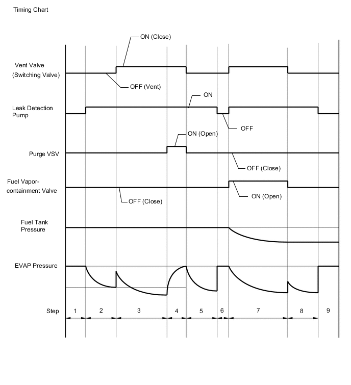
Result Proceed to NEXT -
NEXT
-
-
PERFORM EVAPORATIVE SYSTEM CHECK (MANUAL MODE STEP 1)
-
Select step 1 and wait 10 seconds.
Result Proceed to NEXT
NEXT
-
-
PERFORM EVAPORATIVE SYSTEM CHECK (MANUAL MODE STEP 2)
-
Perform step 2.
-
Check the evaporative pressure 2 seconds after the leak detection pump is activated* (A).
*: The leak detection pump begins to operate at the start of step 2.
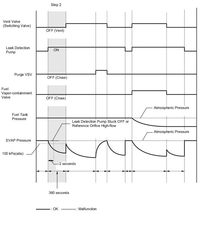
-
Check the evaporative (EVAP) pressure again when it has stabilized (B). This pressure is the first reference pressure.
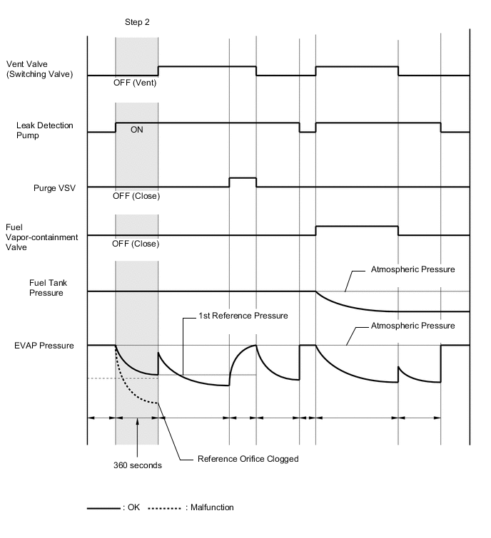
Result Result Suspected Trouble Area Proceed to EVAP pressure in inspection item (B) is between -4.85 and -1.068 kPa(gauge) [-0.7 and -0.155 psi(gauge)] Not yet determined A EVAP pressure in inspection item (B) is -1.068 kPa(gauge) [-0.155 psi(gauge)] or higher
-
Reference orifice high-flow
-
Leak detection pump stuck off
B EVAP pressure in inspection item (B) is less than -4.85 kPa(gauge) [-0.7 psi(gauge)] Reference orifice clogged C -
B
PERFORM ACTIVE TEST USING GTS (ACTIVATE THE VACUUM PUMP) Click here
C
GO TO STEP 54 Click here
A
-
-
PERFORM EVAPORATIVE SYSTEM CHECK (MANUAL MODE STEP 3)
-
Perform step 3.
-
Check the evaporative (EVAP) pressure change in step 3 (A).
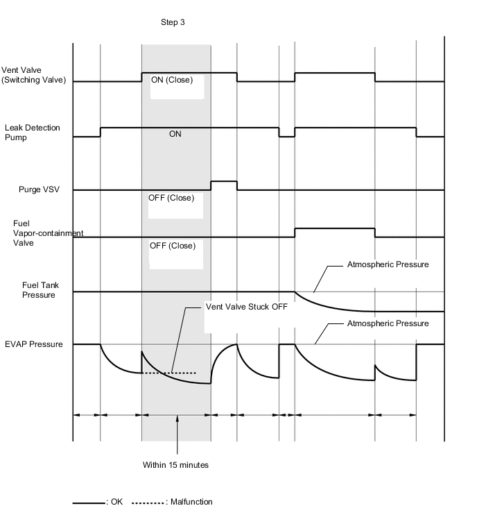
Result Result Suspected Trouble Area Proceed to EVAP pressure change in inspection item (A) is 0.3 kPa(gauge) [0.044 psi(gauge)] or higher Not yet determined A EVAP pressure change in inspection item (A) is less than 0.3 kPa(gauge) [0.044 psi(gauge)] Vent valve (switching valve) stuck off B -
Check the fuel tank pressure change in step 3 (B).
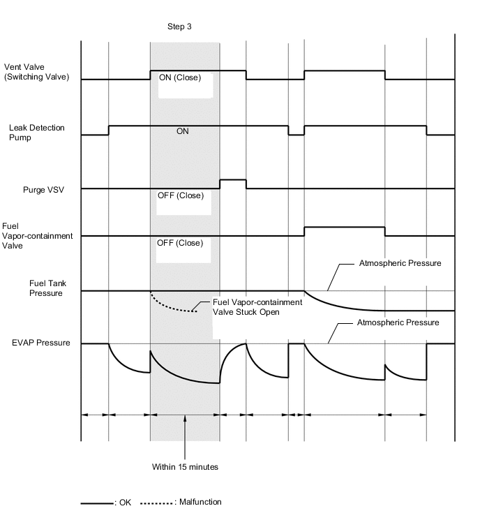
Result Result Suspected Trouble Area Proceed to Fuel tank pressure change in inspection item (B) is less than 0.5 kPa(gauge) [0.073 psi(gauge)] Not yet determined A Fuel tank pressure change in inspection item (B) is higher than 0.5 kPa(gauge) [0.073 psi(gauge)] Fuel vapor-containment valve stuck on (open) C -
Check the EVAP pressure again when it has stabilized. This pressure is the canister leak pressure.
-
Compare the first reference pressure with the canister leak pressure.
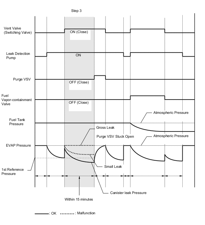
Result Result Suspected Trouble Area Proceed to Lower than first reference pressure Not yet determined A First reference pressure or higher
-
Purge VSV stuck open
-
Leakage from line between purge VSV and canister
D -
B
GO TO STEP 45 Click here
C
CHECK TERMINAL VOLTAGE (POWER SOURCE OF FUEL VAPOR-CONTAINMENT VALVE) Click here
D
GO TO STEP 33 Click here
A
-
-
PERFORM EVAPORATIVE SYSTEM CHECK (MANUAL MODE STEP 4)
-
Perform step 4.
-
Check the evaporative (EVAP) pressure change in step 4 (A).
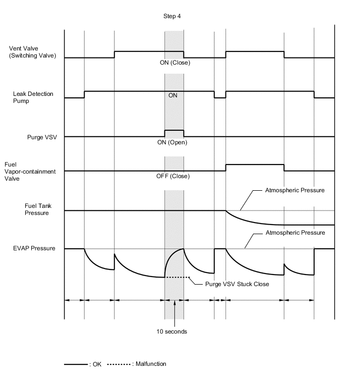
Result Result Suspected Trouble Area Proceed to EVAP pressure increases by 0.3 kPa(gauge) [0.044 psi(gauge)] or higher within 10 seconds of proceeding from step 3 to 4 Not yet determined A Variation in EVAP pressure is less than 0.3 kPa(gauge) [0.044 psi(gauge)] for 10 seconds, after proceeding from step 3 to 4 Purge VSV stuck closed B
B
CHECK VACUUM HOSE (PURGE VSV - INTAKE AIR SURGE TANK ASSEMBLY) Click here
A
-
-
PERFORM EVAPORATIVE SYSTEM CHECK (MANUAL MODE STEP 5)
-
Perform step 5 and wait 60 seconds.
-
Check the evaporative (EVAP) pressure. This pressure is the second reference pressure.
Result Proceed to NEXT
NEXT
-
-
PERFORM EVAPORATIVE SYSTEM CHECK (MANUAL MODE STEP 6)
-
Perform step 6 and wait 5 seconds.
Result Proceed to NEXT
NEXT
-
-
PERFORM EVAPORATIVE SYSTEM CHECK (MANUAL MODE STEP 7)
-
Perform step 7.
-
Check that the tank pressure and EVAP pressure change.
-
Check the tank pressure again when it has stabilized. This pressure is the fuel tank leak pressure.
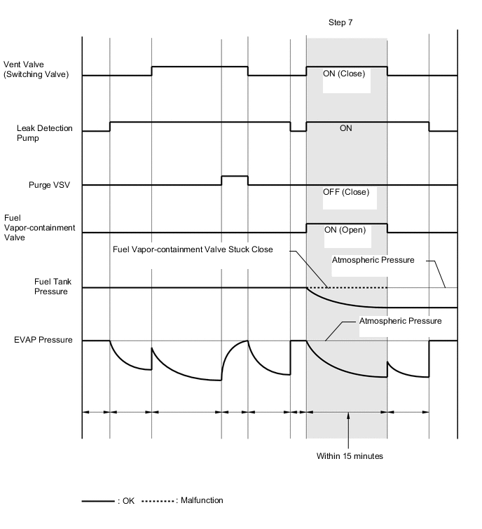
Result Result Suspected Trouble Area Proceed to Fuel tank pressure change is higher than 0.5 kPa(gauge) [0.073 psi(gauge)] and EVAP pressure is higher than 0.9 kPa(gauge) [0.131 psi(gauge)] Not yet determined A Fuel tank pressure change is less than 0.5 kPa(gauge) [0.073 psi(gauge)] and EVAP pressure is less than 0.9 kPa(gauge) [0.131 psi(gauge)] Fuel vapor-containment valve stuck OFF (closed) B
B
GO TO STEP 38 Click here
A
-
-
PERFORM EVAPORATIVE SYSTEM CHECK (MANUAL MODE STEP 8)
-
Perform step 8 and wait 60 seconds.
-
Check the evaporative (EVAP) pressure. This pressure is the third reference pressure.
-
Compare the fuel tank pressure checked in step 7 with the third reference pressure.
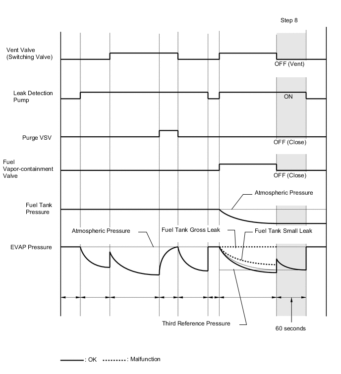
Result Result Suspected Trouble Area Proceed to Lower than third reference pressure Not yet determined A Third reference pressure or higher Leakage from line between fuel vapor-containment valve and fuel tank B
B
CHECK FUEL TANK CAP ASSEMBLY Click here
A
-
-
PERFORM CONFIRMATION DRIVING PATTERN
-
Refer to Confirmation Driving Pattern.
Result Proceed to NEXT
NEXT
PERFORM EVAPORATIVE SYSTEM CHECK AGAIN (AUTOMATIC MODE)
-
-
CHECK FUEL TANK CAP ASSEMBLY
-
Check that the fuel tank cap assembly is correctly installed and confirm that the fuel tank cap assembly meets OEM specifications.
-
Tighten the fuel tank cap assembly firmly (only one click sound could be heard).
Tech Tips
If an EVAP tester is available, check the fuel tank cap assembly using the tester.
-
Remove the fuel tank cap assembly and install it onto a fuel tank cap adapter.
-
Connect an EVAP tester pump hose to the adapter, and pressurize the cap to 3.2 to 3.7 kPa(gauge) [0.46 to 0.54 psi(gauge)] using an EVAP tester pump.
-
Seal the adapter and wait for 2 minutes.
-
Check the pressure. If the pressure is 2 kPa(gauge) [0.29 psi(gauge)] or higher, the fuel tank cap assembly is normal.
Result Result Suspected Trouble Area Proceed to Fuel tank cap assembly correctly installed - A Fuel tank cap assembly loose
-
Fuel tank cap assembly improperly installed
-
Defective fuel tank cap assembly
-
Fuel tank cap assembly does not meet OEM specifications
B -
B
REPLACE FUEL TANK CAP ASSEMBLY Click here
A
-
-
CHECK HOSES (FUEL VAPOR-CONTAINMENT VALVE - FUEL TANK)
-
Connect the EVAP pressure tester tool to the canister pump module with the adapter.
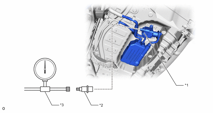
*1 Canister Pump Module *2 Adapter *3 EVAP Pressure Tester Tool - - -
Connect the GTS to the DLC3.
-
Turn the power switch on (IG).
-
Turn the GTS on.
-
Enter the following menus: Powertrain / Engine / Active Test / Activate the Fuel Vapor-Containment Valve.
Powertrain > Engine > Active TestTester Display Activate the Fuel Vapor-Containment Valve -
Turn the fuel vapor-containment valve open (on) using the GTS.
-
Confirm good connection at the canister pump module.
-
Pressurize the EVAP system to between 3.2 and 3.7 kPa(gauge) [24 to 28 mmHg(gauge)].
Note
Higher than 4.7 kPa(gauge) [35 mmHg(gauge)] of pressure will damage the EVAP system. Pay attention to the pressure.
-
Apply soapy water to the piping and connections of the EVAP system.
-
Look for areas where bubbles appear.
Tech Tips
If the system has leaks, a whistling sound will be heard.
Result Proceed to NEXT
NEXT
-
-
REPLACE MALFUNCTIONING PART
-
Repair or replace the leak point.
Result Proceed to NEXT
NEXT
PERFORM EVAPORATIVE SYSTEM CHECK AGAIN (AUTOMATIC MODE)
-
-
REPLACE FUEL TANK CAP ASSEMBLY
-
Replace the fuel tank cap assembly.
Result Proceed to NEXT
NEXT
PERFORM EVAPORATIVE SYSTEM CHECK AGAIN (AUTOMATIC MODE)
-
-
CHECK VACUUM HOSE (PURGE VSV - INTAKE AIR SURGE TANK ASSEMBLY)
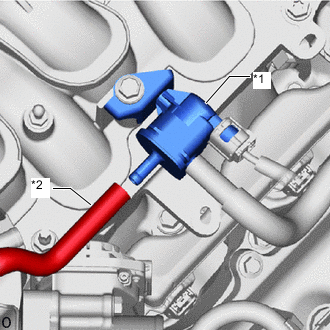
*1 Purge VSV *2 Fuel Vapor Feed Hose Assembly (to Intake Air Surge Tank Assembly)
-
Disconnect the fuel vapor feed hose assembly (connected to the intake air surge tank assembly) from the purge VSV.
-
Connect the GTS to the DLC3.
-
Turn the power switch on (IG).
-
Turn the GTS on.
-
Put the engine in Inspection Mode (2WD for measuring Exhaust Gas).
Powertrain > Hybrid Control > UtilityTester Display Inspection Mode -
Start the engine.
-
Use your finger to confirm that the hose has suction.
Result Test Result Suspected Trouble Area Proceed to Suction applied EVAP hose between purge VSV and intake air surge tank assembly normal A No suction
-
Intake air surge tank assembly port
-
EVAP hose between purge VSV and intake air surge tank assembly
B -
B
INSPECT INTAKE AIR SURGE TANK ASSEMBLY (EVAP PURGE PORT) Click here
A
-
-
PERFORM ACTIVE TEST USING GTS (ACTIVATE THE VSV FOR EVAP CONTROL)
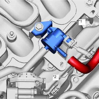
*1 Purge VSV *2 Fuel Vapor Feed Hose Assembly (to Canister)
-
Disconnect the fuel vapor feed hose assembly (connected to the canister) from the purge VSV.
-
Connect the GTS to the DLC3.
-
Turn the power switch on (IG).
-
Turn the GTS on.
-
Put the engine in Inspection Mode (2WD for measuring Exhaust Gas).
Powertrain > Hybrid Control > UtilityTester Display Inspection Mode -
Start the engine.
-
Enter the following menus: Powertrain / Engine / Active Test / Activate the EVAP Purge VSV.
Powertrain > Engine > Active TestTester Display Activate the EVAP Purge VSV -
Using the GTS, turn off the purge VSV (Activate the EVAP Purge VSV: OFF).
-
Use your finger to confirm that the purge VSV has no suction.
-
Using the GTS, turn on the purge VSV (Activate the EVAP Purge VSV: ON).
-
Use your finger to confirm that the purge VSV has suction.
Result Result Suspected Trouble Area Proceed to Suction applied when purge VSV turned off
-
Purge VSV stuck open
-
ECM
A No suction when purge VSV turned on Purge VSV stuck closed No suction when purge VSV turned off, and suction applied when turned on Blockage in the purge line is considered (DTC P04417F or P04419C is output or based on result of step 11):
-
Problems with EVAP hose between canister and purge VSV
-
Canister (charcoal filter inside canister) clogged
-
Trap canister (charcoal filter inside canister)
B Leakage is considered (DTC P04417E or P142100 is output):
Leakage from EVAP line or canister
C -
B
INSPECT CANISTER (CHARCOAL FILTER INSIDE CANISTER) Click here
C
CHECK HOSES (PURGE VSV - CANISTER) Click here
A
-
-
CHECK PURGE VSV
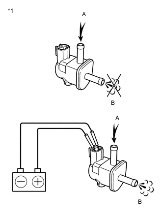
*1 Purge VSV
-
Remove the purge VSV.
-
Apply compressed air to the purge VSV, and confirm that no air flows from A to B as shown in the illustration.
-
Apply auxiliary battery voltage to the terminal of the purge VSV.
-
While applying compressed air, confirm that air flows from A to B as shown in the illustration.
Result Result Proceed to Air flows from A to B only when auxiliary battery voltage applied to purge VSV. Conclusion: purge VSV is normal A No air flows from A to B when auxiliary battery voltage is applied to purge VSV. Conclusion: purge VSV is malfunctioning. B Air flows from A to B when auxiliary battery voltage is not applied to purge VSV. Conclusion: purge VSV is malfunctioning
B
REPLACE PURGE VSV Click here
A
-
-
CHECK TERMINAL VOLTAGE (POWER SOURCE OF PURGE VSV)
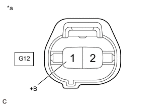
*a Front view of wire harness connector
(to Purge VSV)
-
Disconnect the purge VSV connector.
-
Turn the power switch on (IG).
-
Measure the voltage according to the value(s) in the table below.
Result Tester Connection Condition Specified Condition Suspected Trouble Area Proceed to G12-1 (+B) - Body ground Power switch on (IG) 11 to 14 V Purge VSV power source normal
-
Wire harness or connector between purge VSV and ECM
A Other than result above Wire harness or connectors between purge VSV and auxiliary battery B -
B
GO TO STEP 57 Click here
A
-
-
CHECK HARNESS AND CONNECTOR (PURGE VSV - ECM)
-
Disconnect the purge VSV connector.
-
Disconnect the ECM connector.
-
Measure the resistance according to the value(s) in the table below.
Standard Resistance Tester Connection Condition Specified Condition G12-2 (PRG) - G1-65 (PRG) Always Below 1 Ω G12-2 (PRG) or G1-65 (PRG) - Body ground and other terminals Always 10 kΩ or higher Result Proceed to OK NG
NG
GO TO STEP 57 Click here
OK
-
-
REPLACE ECM
-
Replace the ECM.
Result Proceed to NEXT
NEXT
PERFORM EVAPORATIVE SYSTEM CHECK AGAIN (AUTOMATIC MODE)
-
-
REPLACE PURGE VSV
-
Replace the purge VSV.
Result Proceed to NEXT
NEXT
PERFORM EVAPORATIVE SYSTEM CHECK AGAIN (AUTOMATIC MODE)
-
-
INSPECT CANISTER (CHARCOAL FILTER INSIDE CANISTER)
-
Check for filter blockage in the canister.
OK No blockages in the canister. Result Proceed to OK NG
NG
REPLACE CANISTER Click here
OK
-
-
INSPECT TRAP CANISTER (FUEL OUTLET VALVE ASSEMBLY) (CHARCOAL FILTER INSIDE TRAP CANISTER)
-
Check for filter blockage in the trap canister.
OK No blockages in the trap canister. Result Proceed to OK NG
NG
REPLACE TRAP CANISTER (FUEL OUTLET VALVE ASSEMBLY) Click here
OK
-
-
REPAIR OR REPLACE EVAP PURGE LINE (PURGE VSV - CANISTER)
-
Repair or replace the blocked area in the EVAP purge line.
Result Proceed to NEXT
NEXT
PERFORM EVAPORATIVE SYSTEM CHECK AGAIN (AUTOMATIC MODE)
-
-
REPLACE TRAP CANISTER (FUEL OUTLET VALVE ASSEMBLY)
-
Replace the trap canister.
Note
-
When replacing the trap canister, check the canister interior, canister pump module interior and related pipes for water, fuel and other liquids. If liquids are present, check for disconnections and/or cracks in the following: 1) the pipe from the air inlet port to the canister pump module; 2) the canister filter; and 3) the fuel tank vent hose.
-
Check for filter blockage in the canister filter. if the canister filter has blockages, replace the canister filter.
*1 Fuel Tank Vent Hose *2 Air Inlet Port *3 Vent Hose *4 Fuel Tank *5 Canister Pump Module *6 Canister *7 Trap Canister *8 Fuel Tank Pressure Sensor *9 Fuel Tank Cap Assembly *10 Fuel Vapor-containment Valve *11 Canister Filter - - *a Inspection Area
(Check for disconnection and/or cracks)
- - Result Proceed to NEXT -
NEXT
PERFORM EVAPORATIVE SYSTEM CHECK AGAIN (AUTOMATIC MODE)
-
-
REPLACE CANISTER
-
Replace the canister.
Note
-
When replacing the canister, check the trap canister interior, canister pump module interior and related pipes for water, fuel and other liquids. If liquids are present, check for disconnections and/or cracks in the following: 1) the pipe from the air inlet port to the canister pump module; 2) the canister filter; and 3) the fuel tank vent hose.
-
Check for filter blockage in the canister filter. if the canister filter has blockages, replace the canister filter.
*1 Fuel Tank Vent Hose *2 Air Inlet Port *3 Vent Hose *4 Fuel Tank *5 Canister Pump Module *6 Canister *7 Trap Canister *8 Fuel Tank Pressure Sensor *9 Fuel Tank Cap Assembly *10 Fuel Vapor-containment Valve *11 Canister Filter - - *a Inspection Area
(Check for disconnection and/or cracks)
- - Result Proceed to NEXT -
NEXT
PERFORM EVAPORATIVE SYSTEM CHECK AGAIN (AUTOMATIC MODE)
-
-
CHECK HOSES (PURGE VSV - CANISTER)
-
Connect the EVAP pressure tester tool to the canister pump module with the adapter.
*1 Canister Pump Module *2 Adapter *3 EVAP Pressure Tester Tool - - -
Confirm good connection at the canister pump module.
-
Pressurize the EVAP system to between 3.2 and 3.7 kPa(gauge) [0.46 and 0.54 psi(gauge)].
Note
Higher than 4.7 kPa(gauge) [0.68 psi(gauge)] of pressure will damage the EVAP system. Pay attention to the pressure.
-
Apply soapy water to the piping and connections of the EVAP system.
-
Look for areas where bubbles appear.
Tech Tips
If the system has leaks, a whistling sound will be heard.
Result Proceed to NEXT
NEXT
-
-
REPLACE MALFUNCTIONING PART
-
Repair or replace the leak point.
Result Proceed to NEXT
NEXT
PERFORM EVAPORATIVE SYSTEM CHECK AGAIN (AUTOMATIC MODE)
-
-
INSPECT INTAKE AIR SURGE TANK ASSEMBLY (EVAP PURGE PORT)
-
Disconnect the fuel vapor feed hose assembly from the intake air surge tank assembly.
-
Connect the GTS to the DLC3.
-
Turn the power switch on (IG).
-
Turn the GTS on.
-
Put the engine in Inspection Mode (2WD for measuring Exhaust Gas).
Powertrain > Hybrid Control > UtilityTester Display Inspection Mode -
Start the engine.
-
Use your finger to confirm that the port of the intake air surge tank assembly has suction.
Result Result Suspected Trouble Area Proceed to Suction applied EVAP hose between intake air surge tank assembly and purge VSV A No suction Intake air surge tank assembly B
B
REPAIR OR REPLACE INTAKE AIR SURGE TANK ASSEMBLY (EVAP PURGE PORT) Click here
A
-
-
REPAIR OR REPLACE EVAP HOSE (INTAKE AIR SURGE TANK ASSEMBLY - PURGE VSV)
-
Repair or replace the fuel vapor feed hose assembly.
Result Proceed to NEXT
NEXT
PERFORM EVAPORATIVE SYSTEM CHECK AGAIN (AUTOMATIC MODE)
-
-
REPAIR OR REPLACE INTAKE AIR SURGE TANK ASSEMBLY (EVAP PURGE PORT)
-
Check that the EVAP purge port of the intake air surge tank assembly is not clogged. If necessary, replace the intake air surge tank assembly.
Result Proceed to NEXT
NEXT
PERFORM EVAPORATIVE SYSTEM CHECK AGAIN (AUTOMATIC MODE)
-
-
CHECK TERMINAL VOLTAGE (POWER SOURCE OF FUEL VAPOR-CONTAINMENT VALVE)
-
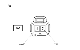
*a Front view of wire harness connector
(to Fuel Vapor-containment Valve)
Disconnect the fuel vapor-containment valve connector.
-
Turn the power switch on (IG).
-
Measure the voltage according to the value(s) in the table below.
Standard Voltage Tester Connection Condition Specified Condition N2-2 (+B) - N2-1 (CCV) Power switch on (IG) 10 to 14 V Result Proceed to OK NG
NG
GO TO STEP 57 Click here
OK
-
-
INSPECT FUEL VAPOR-CONTAINMENT VALVE
-
Inspect the fuel vapor-containment valve.
Result Proceed to OK NG
NG
REPLACE FUEL VAPOR-CONTAINMENT VALVE Click here
OK
-
-
CHECK HARNESS AND CONNECTOR (FUEL VAPOR-CONTAINMENT VALVE - ECM)
-
Disconnect the fuel vapor-containment valve connector.
-
Disconnect the ECM connector.
-
Measure the resistance according to the value(s) in the table below.
Standard Resistance Tester Connection Condition Specified Condition N2-1 (CCV) - G1-33 (CCV2) Always Below 1 Ω N2-1 (CCV) or G1-33 (CCV2) - Body ground and other terminals Always 10 kΩ or higher Result Proceed to OK NG
NG
GO TO STEP 57 Click here
OK
-
-
REPLACE ECM
-
Replace the ECM.
Result Proceed to NEXT
NEXT
PERFORM EVAPORATIVE SYSTEM CHECK AGAIN (AUTOMATIC MODE)
-
-
REPLACE FUEL VAPOR-CONTAINMENT VALVE
-
Replace the fuel vapor-containment valve.
Result Proceed to NEXT
NEXT
PERFORM EVAPORATIVE SYSTEM CHECK AGAIN (AUTOMATIC MODE)
-
-
PERFORM ACTIVE TEST USING GTS (ACTIVATE THE VACUUM PUMP)
-
Connect the GTS to DLC3.
-
Turn the power switch on (IG).
-
Turn the GTS on.
-
Enter the following menus: Powertrain / Engine / Active Test / Activate the Vacuum Pump.
Powertrain > Engine > Active TestTester Display Activate the Vacuum Pump -
Turn the vacuum pump (leak detection pump) on with the GTS.
-
Touch the canister pump module and check if the leak detection pump is moving.
OK Leak detection pump operates Result Proceed to OK NG
NG
CHECK TERMINAL VOLTAGE (CANISTER PUMP MODULE) Click here
OK
-
-
PERFORM ACTIVE TEST USING GTS (ACTIVATE THE VSV FOR VENT VALVE)
-
Connect the GTS to DLC3.
-
Turn the power switch on (IG).
-
Turn the GTS on.
-
Enter the following menus: Powertrain / Engine / Active Test / Activate the VSV for Vent Valve.
Powertrain > Engine > Active TestTester Display Activate the VSV for Vent Valve -
Touch the canister pump module, use the GTS to turn the vent valve on and off, and check if the vent valve is moving.
OK Vent valve vibration can be felt. Result Proceed to OK NG
OK
GO TO STEP 54 Click here
NG
-
-
CHECK CANISTER PUMP MODULE (VENT VALVE POWER SOURCE CIRCUIT)
-

*a Front view of wire harness connector
(to Canister Pump Module)
Disconnect the canister pump module connector.
-
Turn the power switch on (IG).
-
Measure the voltage according to the value(s) in the table below.
Result Tester Connection Switch Condition Specified Condition Suspected Trouble Area Proceed to b2-5 (VLVB) - Body ground Power switch on (IG) 11 to 14 V
-
Wire harness or connector between vent valve and ECM
-
Vent valve
-
Canister (charcoal filter inside canister) clogged
-
Trap canister (filter inside canister clogged)
-
ECM
A Below 3 V
-
Power source wire harness of vent valve
B -
B
GO TO STEP 57 Click here
A
-
-
INSPECT CANISTER PUMP MODULE (VENT VALVE OPERATION)
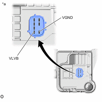
*a Component without harness connected
(Canister Pump Module)
-
Disconnect the canister pump module connector.
-
Apply auxiliary battery voltage to VLVB and VGND terminals of the canister pump module.
-
Touch the canister pump module to confirm the vent valve operation.
Result Condition Tester Result Suspected Trouble Area Proceed to Apply auxiliary battery voltage to terminals VLVB and VGND Operating
-
Wire harness or connector between vent valve and ECM
-
Canister (charcoal filter inside canister) clogged
-
Trap canister (charcoal filter inside canister)
-
ECM
A Not operating
-
Vent valve
B -
B
GO TO STEP 54 Click here
A
-
-
CHECK HARNESS AND CONNECTOR (CANISTER PUMP MODULE - ECM)
-
Disconnect the canister pump module connector.
-
Disconnect the ECM connector.
-
Measure the resistance according to the value(s) in the table below.
Result Tester Connection Condition Test Result Suspected Trouble Area Proceed to b2-1 (VGND) - A58-19 (VPMP) Always Below 1 Ω
-
Canister (charcoal filter inside canister) clogged
-
Trap canister (filter inside canister clogged)
-
ECM
A 10 kΩ or higher Wire harness or connector between ECM and canister pump module B -
B
GO TO STEP 57 Click here
A
-
-
INSPECT CANISTER (CHARCOAL FILTER INSIDE CANISTER)
-
Check for filter blockage in the canister.
OK No blockages in the canister. Result Proceed to OK NG
NG
REPLACE CANISTER Click here
OK
-
-
INSPECT TRAP CANISTER (FUEL OUTLET VALVE ASSEMBLY) (CHARCOAL FILTER INSIDE TRAP CANISTER)
-
Check for filter blockage in the trap canister.
OK No blockages in the trap canister. Result Proceed to OK NG
NG
REPLACE TRAP CANISTER (FUEL OUTLET VALVE ASSEMBLY) Click here
OK
-
-
REPLACE ECM
-
Replace the ECM.
Result Proceed to NEXT
NEXT
PERFORM EVAPORATIVE SYSTEM CHECK AGAIN (AUTOMATIC MODE)
-
-
REPLACE TRAP CANISTER (FUEL OUTLET VALVE ASSEMBLY)
-
Replace the trap canister.
Note
-
When replacing the trap canister, check the canister interior, canister pump module interior and related pipes for water, fuel and other liquids. If liquids are present, check for disconnections and/or cracks in the following: 1) the pipe from the air inlet port to the canister pump module; 2) the canister filter; and 3) the fuel tank vent hose.
-
Check for filter blockage in the canister filter. if the canister filter has blockages, replace the canister filter.
*1 Fuel Tank Vent Hose *2 Air Inlet Port *3 Vent Hose *4 Fuel Tank *5 Canister Pump Module *6 Canister *7 Trap Canister *8 Fuel Tank Pressure Sensor *9 Fuel Tank Cap Assembly *10 Fuel Vapor-containment Valve *11 Canister Filter - - *a Inspection Area
(Check for disconnection and/or cracks)
- - Result Proceed to NEXT -
NEXT
PERFORM EVAPORATIVE SYSTEM CHECK AGAIN (AUTOMATIC MODE)
-
-
REPLACE CANISTER
-
Replace the canister.
Note
-
When replacing the canister, check the trap canister interior, canister pump module interior and related pipes for water, fuel and other liquids. If liquids are present, check for disconnections and/or cracks in the following: 1) the pipe from the air inlet port to the canister pump module; 2) the canister filter; and 3) the fuel tank vent hose.
-
Check for filter blockage in the canister filter. if the canister filter has blockages, replace the canister filter.
*1 Fuel Tank Vent Hose *2 Air Inlet Port *3 Vent Hose *4 Fuel Tank *5 Canister Pump Module *6 Canister *7 Trap Canister *8 Fuel Tank Pressure Sensor *9 Fuel Tank Cap Assembly *10 Fuel Vapor-containment Valve *11 Canister Filter - - *a Inspection Area
(Check for disconnection and/or cracks)
- - Result Proceed to NEXT -
NEXT
PERFORM EVAPORATIVE SYSTEM CHECK AGAIN (AUTOMATIC MODE)
-
-
CHECK TERMINAL VOLTAGE (CANISTER PUMP MODULE)
-
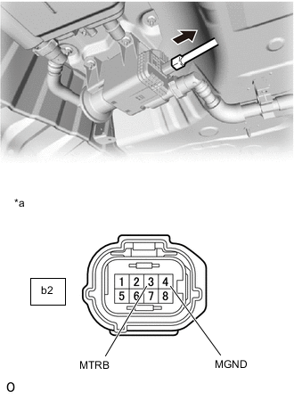
*a Front view of wire harness connector
(to Canister Pump Module)
Disconnect the canister pump module connector.
-
Turn the power switch on (IG).
-
Measure the voltage according to the value(s) in the table below.
Standard Voltage Tester Connection Condition Specified Condition b2-3 (MTRB) - b2-4 (MGND) Power switch on (IG) 10 to 14 V Power switch off Below 3 V Result Proceed to OK NG
NG
CHECK HARNESS AND CONNECTOR (CANISTER PUMP MODULE - ECM, BODY GROUND) Click here
OK
-
-
REPLACE CANISTER PUMP MODULE
-
Replace the canister pump module.
Result Proceed to NEXT
NEXT
PERFORM EVAPORATIVE SYSTEM CHECK AGAIN (AUTOMATIC MODE)
-
-
CHECK HARNESS AND CONNECTOR (CANISTER PUMP MODULE - ECM, BODY GROUND)
-
Disconnect the canister pump module connector.
-
Disconnect the ECM connector.
-
Measure the resistance according to the value(s) in the table below.
Standard Resistance Tester Connection Condition Specified Condition b2-3 (MTRB) - A58-21 (MPMP) Always Below 1 Ω b2-4 (MGND) - Body ground Always Below 1 Ω b2-3 (MTRB) or A58-21 (MPMP) - Body ground and other terminals Always 10 kΩ or higher Result Proceed to OK NG
NG
REPAIR OR REPLACE HARNESS OR CONNECTOR Click here
OK
-
-
REPLACE ECM
-
Replace the ECM.
Result Proceed to NEXT
NEXT
PERFORM EVAPORATIVE SYSTEM CHECK AGAIN (AUTOMATIC MODE)
-
-
REPAIR OR REPLACE HARNESS OR CONNECTOR
-
Repair or replace harness or connector.
Result Proceed to NEXT
NEXT
PERFORM EVAPORATIVE SYSTEM CHECK AGAIN (AUTOMATIC MODE)
-