TELEMATICS SYSTEM(for G-BOOK) Telematics Transceiver Malfunction
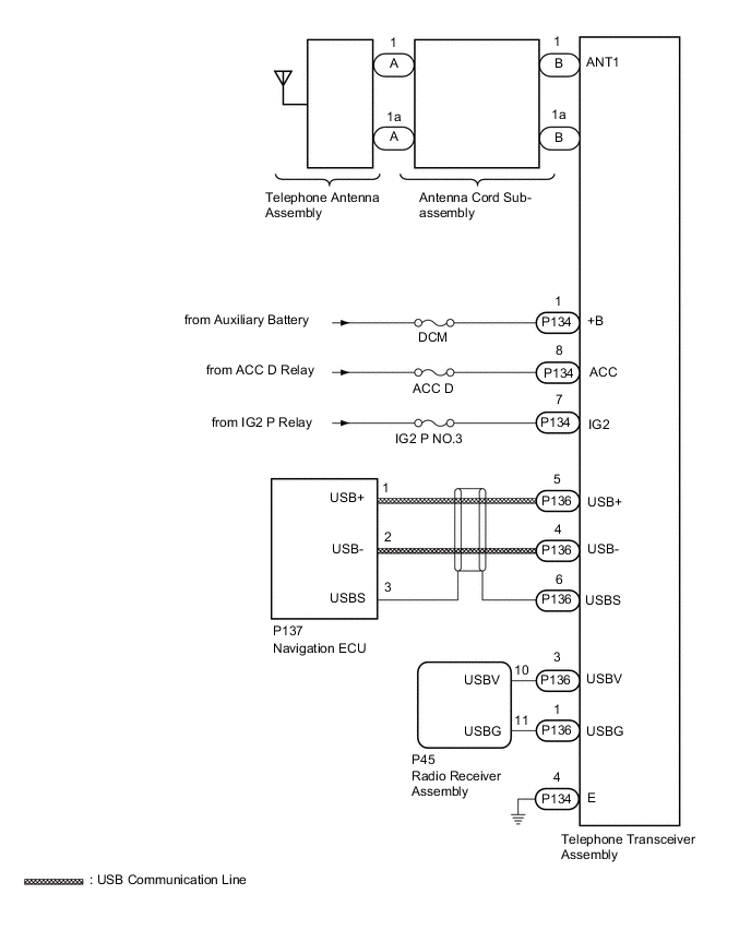
WIRING DIAGRAM
CAUTION / NOTICE / HINT
Note
-
Inspect the fuses for circuits related to this system before performing the following procedure.
-
Depending on the parts that are replaced during vehicle inspection or maintenance, performing initialization, registration or calibration may be needed. Refer to Precaution for G-BOOK
-
When replacing the telephone transceiver assembly, make sure to replace it with a new one.
-
When replacing the radio receiver assembly or navigation ECU, always replace it with a new one.
If a radio receiver assembly or navigation ECU which was installed to another vehicle is used, the following may occur:
-
A communication malfunction DTC may be stored.
-
The radio receiver assembly or navigation ECU may not operate normally.
PROCEDURE
-
MOVE VEHICLE
-
If the vehicle is outside the communication service area, move the vehicle into a communication service area, wait for a while and perform the operation again.
Result Proceed to NEXT
NEXT 
-
-
CHECK DTC OUTPUT
-
Clear the DTCs.
Body Electrical > Navigation System > Clear DTCs -
Recheck for DTCs and check if the same DTC is output again.
Body Electrical > Navigation System > Trouble CodesResult Result Proceed to No DTCs are output. A DTCs are output. B
B 
GO TO DIAGNOSTIC TROUBLE CODE CHART Click here
A
-
-
PERFORM DCM CHECK
-
DCM Check
-
Enter diagnostic mode.
-
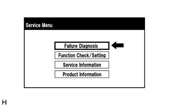
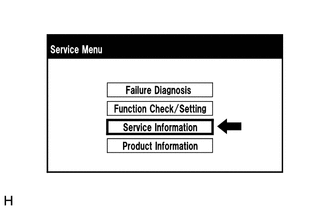
Select "Failure Diagnosis" on the "Service Menu" screen.
-
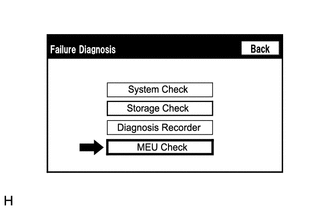
Select "MEU Check" from the "Failure Diagnosis" screen.
-
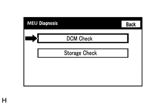
Select "DCM Check" from the "MEU Diagnosis" screen.
-
Select "DCM Check" to perform the DCM Check.
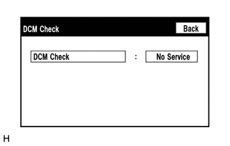
Result Result Proceed to DCM Check cannot be performed. A "OK" is displayed for the result of DCM Check. "OFF LINE" is displayed for the result of DCM Check. B "No Service" is displayed for the result of DCM Check. C "NO CARRIER" is displayed for the result of DCM Check. D "RESTRICTION" is displayed for the result of DCM Check. E "NO ANT" is displayed for the result of DCM Check. F "ERROR" is displayed for the result of DCM Check. G "PLL NG" is displayed for the result of DCM Check. H "TIME OUT" is displayed for the result of DCM Check. I Tech Tips
If the vehicle is moved while the screen is displayed, select "Back" to renew the result.
-
B
MOVE VEHICLE
C 
CHECK CONTRACT FLAG Click here
D
CONTACT G-BOOK SUPPORT CENTER
E
PERFORM OPERATION (AFTER WAITING FOR 10 TO 30 MINUTES)
F
GO TO STEP 10 Click here
G
CHECK PROBLEM SYMPTOM (POWER SWITCH OFF AND ON [ACC]) Click here
H
CHECK HARNESS AND CONNECTOR (TELEPHONE TRANSCEIVER ASSEMBLY POWER SOURCE) Click here
I
PERFORM DCM CHECK AGAIN
A
-
-
CONTACT G-BOOK SUPPORT CENTER
-
Check the contract flag.
-
Enter diagnostic mode.
-
Select "Service Information" on the "Service Menu" screen.
-
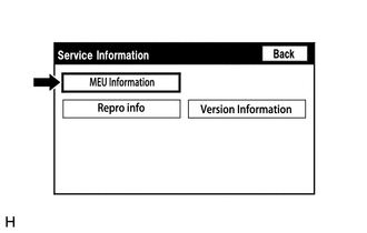
Select "MEU Information" from the "Service Information" screen.
-
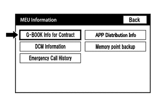
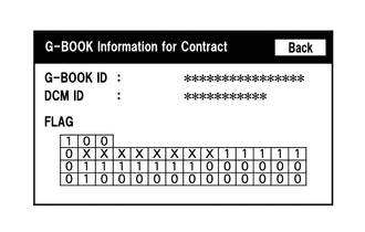
Select "G-BOOK Info for Contract" on the "MEU Information" screen.
-
Check the flag information item.
-
-

Check the device information.
-
Select "DCM Information" on the "MEU Information" screen.
-
Check the following items on the "DCM Information" screen.

Item Content Tel No Check if the telephone transceiver assembly phone number is displayed. If the number is displayed, record it. DCM Serial Record the telephone transceiver assembly serial number.
-
-
Contact the G-BOOK support center.
-
Contact the G-BOOK support center and inform them of the following:
-
Phenomenon: Communication has been initialized but communication is not possible.
-
Flag information
-
Telephone number (Tel No): Not displayed / Displayed number
-
Serial number (DCM Serial): Displayed number
-
VIN
Tech Tips
The G-BOOK support center will perform an investigation and provide the results.
-
-
Check for problem symptoms after receiving a call from the G-BOOK support center.
Result Result Proceed to System returns to normal. A Problem symptom recurs. B -
A
CHECK PROBLEM SYMPTOM AFTER POWER SWITCH IS TURNED OFF TO ON (ACC)
B
-
-
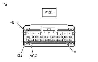
CHECK HARNESS AND CONNECTOR (TELEPHONE TRANSCEIVER ASSEMBLY - BATTERY AND BODY GROUND)
-
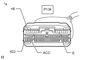
*a Front view of wire harness connector
(to Telephone Transceiver Assembly)
Disconnect the telephone transceiver assembly connector.
-
Measure the resistance according to the value(s) in the table below.
Standard Resistance Tester Connection Condition Specified Condition P134-4 (E) - Body ground Always Below 1 Ω -
Measure the voltage according to the value(s) in the table below.
Standard Voltage Tester Connection Switch Condition Specified Condition P134-1 (+B) - Body ground Power switch off 11 to 14 V P134-8 (ACC) - Body ground Power switch on (ACC) 11 to 14 V P134-7 (IG2) - Body ground Power switch on (IG) 11 to 14 V Result Proceed to OK NG
NG
REPAIR OR REPLACE HARNESS OR CONNECTOR
OK
-
-
CHECK HARNESS AND CONNECTOR (RADIO RECEIVER ASSEMBLY - TELEPHONE TRANSCEIVER ASSEMBLY)
-
Disconnect the P45 radio receiver assembly connector.
-
Disconnect the P136 telephone transceiver assembly connector.
-
Measure the resistance according to the value(s) in the table below.
Standard Resistance Tester Connection Condition Specified Condition P45-10 (USBV) - P136-3 (USBV) Always Below 1 Ω P45-11 (USBG) - P136-1 (USBG) Always Below 1 Ω P45-10 (USBV) - Body ground Always 10 kΩ or higher P45-11 (USBG) - Body ground Always 10 kΩ or higher Result Proceed to OK NG
NG
REPAIR OR REPLACE HARNESS OR CONNECTOR
OK
-
-
CHECK RADIO RECEIVER ASSEMBLY (USBV, USBG)
-
Disconnect the telephone transceiver assembly connector.
-
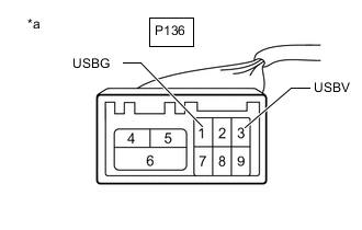
*a Front view of wire harness connector
(to Telephone Transceiver Assembly)
Measure the resistance according to the value(s) in the table below.
Standard Resistance Tester Connection Condition Specified Condition P136-1 (USBG) - Body ground Always Below 1 Ω -
Measure the voltage according to the value(s) in the table below.
Standard Voltage Tester Connection Switch Condition Specified Condition P136-3 (USBV) - P136-1 (USBG) Power switch on (ACC) 4.75 to 5.25 V Result Proceed to OK NG
NG
REPLACE RADIO RECEIVER ASSEMBLY Click here
OK
-
-
CHECK HARNESS AND CONNECTOR (TELEPHONE TRANSCEIVER ASSEMBLY - NAVIGATION ECU)
-
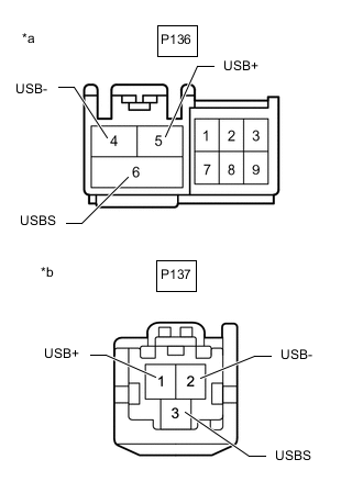
*a Front view of wire harness connector
(to Telephone Transceiver Assembly)
*b Front view of wire harness connector
(to Navigation ECU)
Disconnect the P136 telephone transceiver assembly connector.
-
Disconnect the P137 navigation ECU connector.
-
Measure the resistance according to the value(s) in the table below.
Standard Resistance Tester Connection Condition Specified Condition P136-4 (USB-) - P137-2 (USB-) Always Below 1 Ω P136-5 (USB+) - P137-1 (USB+) Always Below 1 Ω P136-6 (USBS) - P137-3 (USBS) Always Below 1 Ω P136-4 (USB-) - Body ground Always 10 kΩ or higher P136-5 (USB+) - Body ground Always 10 kΩ or higher P136-6 (USBS) - Body ground Always 10 kΩ or higher Result Proceed to OK NG
NG
REPAIR OR REPLACE HARNESS OR CONNECTOR
OK
-
-
CHECK RECEPTION LEVEL
-
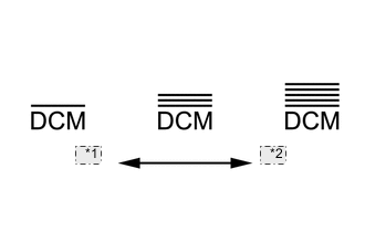
*1 poor *2 good Check the reception level.
-
Check the reception level of the telephone transceiver assembly.
Tech Tips
-
Check if the reception level is significantly lower by comparing it to a China Telecom cellular phone.
-
If there is no China Telecom cellular phone available, move the vehicle to a location where the reception level indicator shows 3 bars or more.
-
If a problem occurred because the G-BOOK contract has not been completed, proceed to the contract procedure and check the telephone transceiver assembly reception level on the screen during the contract procedure.
-
Result Result Proceed to
-
The reception level is not lower than a China Telecom cellular phone.
-
3 or more bars are displayed for the reception level.
A
-
The reception level is lower than a China Telecom cellular phone.
-
Cannot reach 3 or more bars for the reception level even after moving the vehicle.
B -
A
GO TO STEP 12 Click here
B
-
-
INSPECT TELEPHONE ANTENNA ASSEMBLY
-
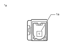
*a Telephone Antenna Assembly Remove the telephone antenna assembly.
-
Measure the resistance according to the value(s) in the table below.
Standard Resistance Tester Connection Condition Specified Condition 1 - 1a Always 9 to 11 kΩ Result Proceed to OK NG
NG
REPLACE TELEPHONE ANTENNA ASSEMBLY Click here
OK
-
-
INSPECT ANTENNA CORD SUB-ASSEMBLY
-
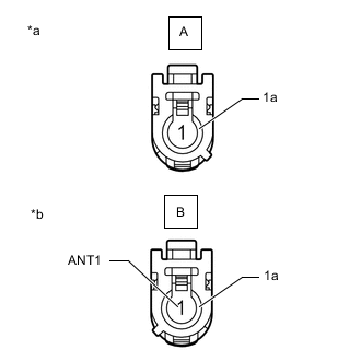
*a Front view of wire harness connector
(to Telephone Antenna Assembly)
*b Front view of wire harness connector
(to Telephone Transceiver Assembly)
Disconnect the antenna connector from the telephone antenna assembly connector.
-
Disconnect the antenna connector from the telephone transceiver assembly connector.
-
Measure the resistance according to the value(s) in the table below.
Standard Resistance Tester Connection Condition Specified Condition A-1 - B-1 (ANT) Always Below 1 Ω A-1a - B-1a Always Below 1 Ω A-1 - Body ground Always 10 kΩ or higher A-1a - Body ground Always 10 kΩ or higher Result Proceed to OK NG
NG
REPLACE ANTENNA CORD SUB-ASSEMBLY Click here
OK
-
-
CHECK TELEPHONE TRANSCEIVER ASSEMBLY
-
Replace the telephone transceiver assembly with a new one and check if the same problem occurs again.
OK Same problem does not occur. Result Proceed to OK NG
OK
END (TELEPHONE TRANSCEIVER ASSEMBLY IS DEFECTIVE)
NG
REPLACE RADIO RECEIVER ASSEMBLY Click here
-
-
CHECK CONTRACT FLAG
-
Check the contract flag.
-
Enter diagnostic mode.
-
Select "Service Information" on the "Service Menu" screen.
-
Select "MEU Information" from the "Service Information" screen.
-
Select "G-BOOK Info for Contract" on the "MEU Information" screen.
-
Check if the flag information indicates "1" as shown in the illustration.
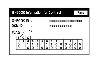
*a Cell to be Checked -
Turn the power switch off and then on (ACC).
-
Check again if the flag information indicates "1" as shown in the illustration.
-
-
Recheck the problem symptom.
-
Select G-BOOK.com and perform the contract procedure again.
-
Check for the problem symptom.
Result Result Proceed to Contract flag indicates "1" and the system returns to normal. A Contract flag indicates "1" but the problem symptom recurs. B Contract flag does not indicate "1" and the problem symptom recurs. C -
A
END
B
REPLACE TELEPHONE TRANSCEIVER ASSEMBLY Click here
C
CONTACT G-BOOK SUPPORT CENTER
-
-
CHECK PROBLEM SYMPTOM (POWER SWITCH OFF AND ON [ACC])
-
Check for the problem symptom.
-
Turn the power switch off and then on (ACC).
-
Check if the problem symptom recurs.
Result Result Proceed to System returns to normal. A System does not return to normal. B
-
A
END
B
REPLACE TELEPHONE TRANSCEIVER ASSEMBLY Click here
-
-
CHECK HARNESS AND CONNECTOR (TELEPHONE TRANSCEIVER ASSEMBLY POWER SOURCE)
*a Front view of wire harness connector
(to Telephone Transceiver Assembly)
-
Disconnect the telephone transceiver assembly connector.
-
Measure the resistance according to the value(s) in the table below.
Standard Resistance Tester Connection Condition Specified Condition P134-4 (E) - Body ground Always Below 1 Ω -
Measure the voltage according to the value(s) in the table below.
Standard Voltage Tester Connection Switch Condition Specified Condition P134-1 (+B) - P134-4 (E) Power switch off 11 to 14 V P134-8 (ACC) - P134-4 (E) Power switch on (ACC) 11 to 14 V P134-7 (IG2) - P134-4 (E) Power switch on (IG) 11 to 14 V Result Proceed to OK NG
OK
REPLACE TELEPHONE TRANSCEIVER ASSEMBLY Click here
NG
REPAIR OR REPLACE HARNESS OR CONNECTOR
-