TELEMATICS SYSTEM(for G-BOOK), Diagnostic DTC:B15C6
| DTC Code | DTC Name |
|---|---|
| B15C6 | Ignition Switch Signal Malfunction |
DESCRIPTION
If vehicle movement (10 km/h (6 mph) or more for 10 seconds) is detected based on the location data sent from the navigation ECU even when the telephone transceiver assembly detects that the power switch is off, this DTC will be stored.
| DTC No. | Detection Item | DTC Detection Condition | Trouble Area |
|---|---|---|---|
| B15C6 | Ignition Switch Signal Malfunction | IG signal error |
|
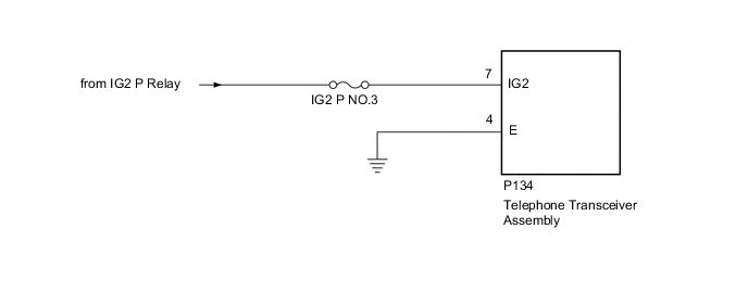
WIRING DIAGRAM
CAUTION / NOTICE / HINT
Note
-
Inspect the fuse for circuits related to this system before performing the following procedure.
-
Depending on the parts that are replaced during vehicle inspection or maintenance, performing initialization, registration or calibration may be needed. Refer to Precaution for G-BOOK.
-
When replacing the telephone transceiver assembly, make sure to replace it with a new one.
PROCEDURE
-
CHECK DTC OUTPUT
-
Clear the DTCs.
Body Electrical > Navigation System > Clear DTCs -
Recheck for DTCs and check if the same DTC is output again.
Body Electrical > Navigation System > Trouble CodesResult Result Proceed to B15C6 is not output. A B15C6 is output. B
A 
USE SIMULATION METHOD TO CHECK Click here
B 
-
-
CHECK HARNESS AND CONNECTOR (TELEPHONE TRANSCEIVER ASSEMBLY - BATTERY AND BODY GROUND)
-
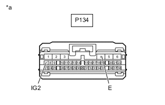
*a Front view of wire harness connector
(to Telephone Transceiver Assembly)
Disconnect the telephone transceiver assembly connector.
-
Measure the resistance according to the value(s) in the table below.
Standard Resistance Tester Connection Condition Specified Condition P134-4 (E) - Body ground Always Below 1 Ω -
Measure the voltage according to the value(s) in the table below.
Standard Voltage Tester Connection Switch Condition Specified Condition P134-7 (IG2) - Body ground Power switch on (IG) 11 to 14 V Result Proceed to OK NG
OK
REPLACE TELEPHONE TRANSCEIVER ASSEMBLY Click here
NG
REPAIR OR REPLACE HARNESS OR CONNECTOR
-