TELEPHONE ANTENNA INSTALLATION
CAUTION / NOTICE / HINT
PROCEDURE
-
INSTALL NO. 2 ROOF WIRE
-
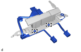
Attach the clamps to install the No. 2 roof wire.
-
-
INSTALL TELEPHONE ANTENNA ASSEMBLY
-
Attach the guides A and clip.
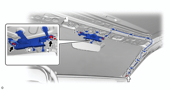

Nut 
Connector -
Install the 2 nuts.
- Torque:
- 14 N*m { 143 kgf*cm, 10 ft.*lbf }
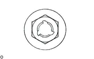
Tech Tips
If the removed nut is the same shape as that shown in the illustration, replace it the supplied replacement part.
-
Attach the clamps to install the telephone antenna assembly and connect the 3 connectors.
-
-
INSTALL ROOF HEADLINING ASSEMBLY
-
CONNECT CABLE TO NEGATIVE AUXILIARY BATTERY TERMINAL
Note
When disconnecting the cable, some systems need to be initialized after the cable is reconnected.
-
INSTALL NO. 2 DECK BOARD
-
PERFORM DIAGNOSTIC SYSTEM CHECK
-
CHECK SRS WARNING LIGHT