SFI SYSTEM(w/ Canister Pump Module), Diagnostic DTC:P035113, P035213, P035313, P035413, P035513, P035613
| DTC Code | DTC Name |
|---|---|
| P035113 | Ignition Coil "A" Circuit Open |
| P035213 | Ignition Coil "B" Circuit Open |
| P035313 | Ignition Coil "C" Circuit Open |
| P035413 | Ignition Coil "D" Circuit Open |
| P035513 | Ignition Coil "E" Circuit Open |
| P035613 | Ignition Coil "F" Circuit Open |
DESCRIPTION
Tech Tips
-
These DTCs indicate malfunctions relating to the primary circuit.
-
If DTC P035113 is output, check the No. 1 ignition coil assembly circuit.
-
If DTC P035213 is output, check the No. 2 ignition coil assembly circuit.
-
If DTC P035313 is output, check the No. 3 ignition coil assembly circuit.
-
If DTC P035413 is output, check the No. 4 ignition coil assembly circuit.
-
If DTC P035513 is output, check the No. 5 ignition coil assembly circuit.
-
If DTC P035613 is output, check the No. 6 ignition coil assembly circuit.
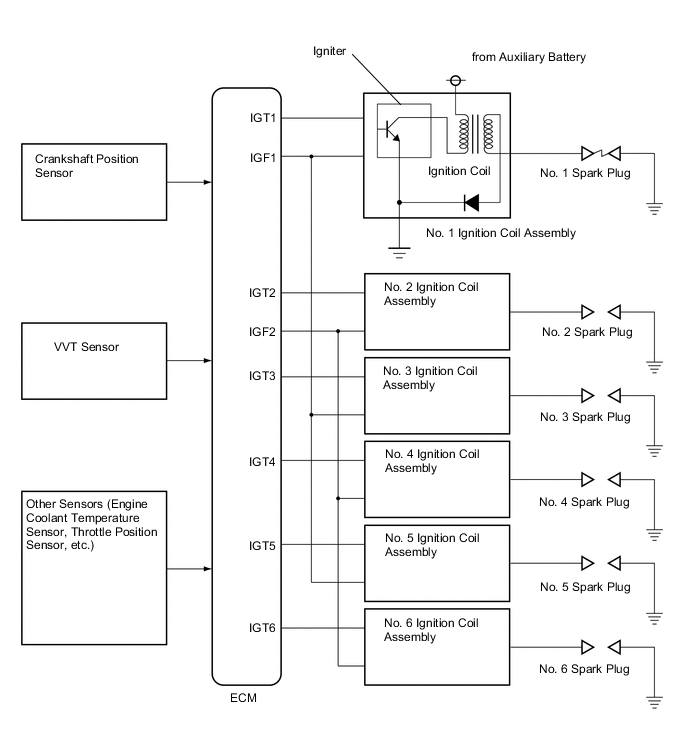
A Direct Ignition System (DIS) is used on this vehicle.
The DIS is a 1-cylinder ignition system in which each cylinder is ignited by one ignition coil assembly and one spark plug is connected to the end of each secondary wiring. A powerful voltage, generated in the secondary wiring, is applied directly to each spark plug. The spark of the spark plugs passes from the center electrode to the ground electrodes.
The ECM determines the ignition timing and transmits the ignition (IGT) signals to each cylinder. Using the IGT signal, the ECM turns the power transistor inside the igniter on and off. The power transistor, in turn, switches the current supplied to the primary coil on and off. When the current to the primary coil is cut off, a powerful voltage is generated in the secondary coil. This voltage is applied to the spark plugs, causing them to spark inside the cylinders. As the ECM cuts the current to the primary coil, the igniter sends back an ignition confirmation (IGF) signal to the ECM for each cylinder ignition.
| DTC No. | Detection Item | DTC Detection Condition | Trouble Area | MIL | Memory | Note |
|---|---|---|---|---|---|---|
| P035113 | Ignition Coil "A" Circuit Open | No IGF signal to the ECM while the engine is running (1 trip detection logic). |
|
Comes on | DTC stored | SAE: P0351 |
| P035213 | Ignition Coil "B" Circuit Open | No IGF signal to the ECM while the engine is running (1 trip detection logic). |
|
Comes on | DTC stored | SAE: P0352 |
| P035313 | Ignition Coil "C" Circuit Open | No IGF signal to the ECM while the engine is running (1 trip detection logic). |
|
Comes on | DTC stored | SAE: P0353 |
| P035413 | Ignition Coil "D" Circuit Open | No IGF signal to the ECM while the engine is running (1 trip detection logic). |
|
Comes on | DTC stored | SAE: P0354 |
| P035513 | Ignition Coil "E" Circuit Open | No IGF signal to the ECM while the engine is running (1 trip detection logic). |
|
Comes on | DTC stored | SAE: P0355 |
| P035613 | Ignition Coil "F" Circuit Open | No IGF signal to the ECM while the engine is running (1 trip detection logic). |
|
Comes on | DTC stored | SAE: P0356 |
-
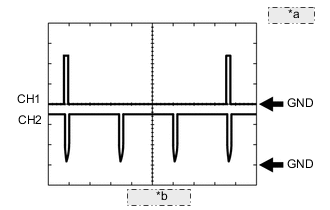
*a 2 V/DIV. *b 20 ms./DIV. Reference: Inspection using an oscilloscope.
Tech Tips
-
The correct waveform is as shown.
-
While idling the engine, check the waveform between terminals IGT (1 to 6) and E1, and IGF (1 or 2) and E1 of the ECM connector.
ECM Terminal Name CH1: Between IGT (1 to 6) and E1
CH2: Between IGF (1 or 2) and E1
Tester Range 2 V/DIV., 20 ms./DIV. Condition Idling with warm engine -
MONITOR DESCRIPTION
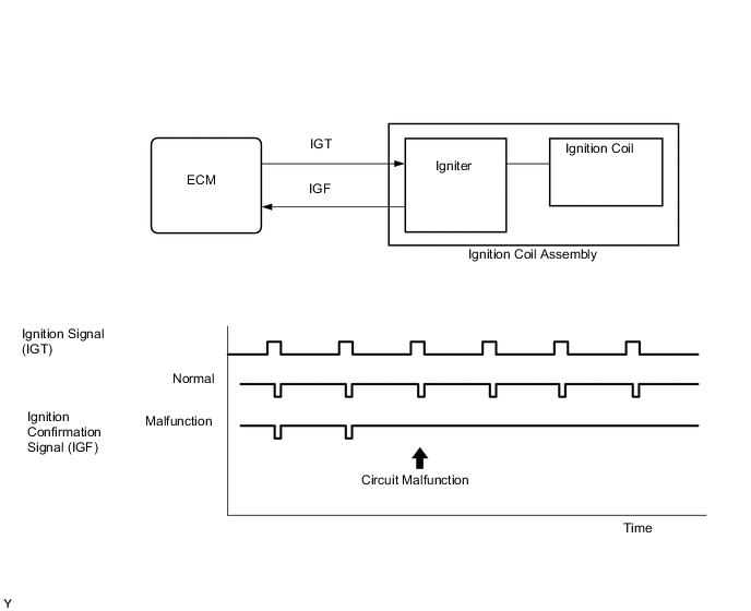
If the ECM does not receive any IGF signals despite transmitting the IGT signal, it interprets this as a malfunction of an igniter and stores a DTC.
MONITOR STRATEGY
| Required Sensors/Components (Main) | Igniter |
| Required Sensors/Components (Related) | Crankshaft position sensor |
| Frequency of Operation | Continuous |
CONFIRMATION DRIVING PATTERN
-
Connect the GTS to the DLC3.
-
Turn the power switch on (IG).
-
Turn the GTS on.
-
Clear the DTCs (even if no DTCs are stored, perform the clear DTC procedure).
-
Turn the power switch off and wait for at least 30 seconds.
-
Turn the power switch on (IG).
-
Turn the GTS on.
-
Put the engine in Inspection Mode (2WD for measuring Exhaust Gas).
-
Start the engine.
-
Idle the engine for 10 seconds or more [A].
-
Enter the following menus: Powertrain / Engine / Trouble Codes [B].
-
Read the pending DTCs.
Tech Tips
-
If a pending DTC is output, the system is malfunctioning.
-
If a pending DTC is not output, perform the following procedure.
-
-
Enter the following menus: Powertrain / Engine / Utility / All Readiness.
-
Input the DTC: P035113, P035213, P035313, P035413, P035513 or P035613.
-
Check the DTC judgment result.
GTS Display Description NORMAL
-
DTC judgment completed
-
System normal
ABNORMAL
-
DTC judgment completed
-
System abnormal
INCOMPLETE
-
DTC judgment not completed
-
Perform driving pattern after confirming DTC enabling conditions
Tech Tips
-
If the judgment result shows NORMAL, the system is normal.
-
If the judgment result shows ABNORMAL, the system is malfunctioning.
-
If the judgment result shows INCOMPLETE, perform steps [A] and [B] again.
-
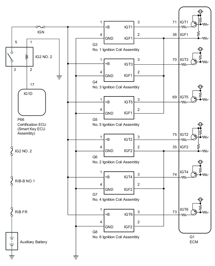
WIRING DIAGRAM
CAUTION / NOTICE / HINT
Note
-
Inspect the fuses for circuits related to this system before performing the following procedure.
-
Vehicle Control History may be stored in the hybrid vehicle control ECU if the engine is malfunctioning. Certain vehicle condition information is recorded when Vehicle Control History is stored. Reading the vehicle conditions recorded in both the freeze frame data and Vehicle Control History can be useful for troubleshooting.
(Select Powertrain in Health Check and then check the time stamp data.)
-
If any "Engine Malfunction" Vehicle Control History item has been stored in the hybrid vehicle control ECU, make sure to clear it. However, as all Vehicle Control History items are cleared simultaneously, if any Vehicle Control History items other than "Engine Malfunction" are stored, make sure to perform any troubleshooting for them before clearing Vehicle Control History.
Tech Tips
Read freeze frame data using the GTS. The ECM records vehicle and driving condition information as freeze frame data the moment a DTC is stored. When troubleshooting, freeze frame data can help determine if the vehicle was moving or stationary, if the engine was warmed up or not, if the air fuel ratio was lean or rich, and other data from the time the malfunction occurred.
PROCEDURE
-
CLEAR DTC
-
Connect the GTS to the DLC3.
-
Turn the power switch on (IG).
-
Turn the GTS on.
-
Clear the DTCs.
Powertrain > Engine > Clear DTCs -
Turn the power switch off and wait for at least 30 seconds.
Result Proceed to NEXT
NEXT 
-
-
CHECK WHETHER DTC OUTPUT RECURS (DTC P035113, P035213, P035313, P035413, P035513 OR P035613)
-
Shuffle the arrangement of the ignition coil assemblies (among No. 1 to No. 6 cylinders).
Note
Do not change the location of the connectors.
-
Drive the vehicle in accordance with the driving pattern described in Confirmation Driving Pattern.
-
Enter the following menus: Powertrain / Engine / Trouble Codes.
-
Read the DTCs.
Powertrain > Engine > Trouble CodesResult Result Proceed to Same DTC output A Different ignition coil DTC output B
B 
REPLACE IGNITION COIL ASSEMBLY Click here
A
-
-
CHECK TERMINAL VOLTAGE (POWER SOURCE OF IGNITION COIL ASSEMBLY)
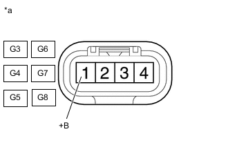
*a Front view of wire harness connector
(to Ignition Coil Assembly)
-
Disconnect the ignition coil assembly connector.
-
Turn the power switch on (IG).
-
Measure the voltage according to the value(s) in the table below.
Standard Voltage Tester Connection Condition Specified Condition G3-1 (+B) - Body ground Power switch on (IG) 11 to 14 V G6-1 (+B) - Body ground Power switch on (IG) 11 to 14 V G4-1 (+B) - Body ground Power switch on (IG) 11 to 14 V G7-1 (+B) - Body ground Power switch on (IG) 11 to 14 V G5-1 (+B) - Body ground Power switch on (IG) 11 to 14 V G8-1 (+B) - Body ground Power switch on (IG) 11 to 14 V Result Proceed to OK NG
NG 
CHECK HARNESS AND CONNECTOR (IG2 NO. 2 RELAY - IGNITION COIL ASSEMBLY) Click here
OK
-
-
CHECK HARNESS AND CONNECTOR (IGNITION COIL ASSEMBLY - BODY GROUND)
-
Disconnect the ignition coil assembly connector.
-
Measure the resistance according to the value(s) in the table below.
Standard Resistance Tester Connection Condition Specified Condition G3-4 (GND) - Body ground Always Below 1 Ω G6-4 (GND) - Body ground Always Below 1 Ω G4-4 (GND) - Body ground Always Below 1 Ω G7-4 (GND) - Body ground Always Below 1 Ω G5-4 (GND) - Body ground Always Below 1 Ω G8-4 (GND) - Body ground Always Below 1 Ω Result Proceed to OK NG
NG
REPAIR OR REPLACE HARNESS OR CONNECTOR
OK
-
-
CHECK HARNESS AND CONNECTOR (IGNITION COIL ASSEMBLY - ECM)
-
Disconnect the ignition coil assembly connector.
-
Disconnect the ECM connector.
-
Measure the resistance according to the value(s) in the table below.
Standard Resistance Tester Connection Condition Specified Condition G3-2 (IGF1) - G1-36 (IGF1) Always Below 1 Ω G6-2 (IGF2) - G1-35 (IGF2) Always Below 1 Ω G4-2 (IGF1) - G1-36 (IGF1) Always Below 1 Ω G7-2 (IGF2) - G1-35 (IGF2) Always Below 1 Ω G5-2 (IGF1) - G1-36 (IGF1) Always Below 1 Ω G8-2 (IGF2) - G1-35 (IGF2) Always Below 1 Ω G3-3 (IGT1) - G1-71 (IGT1) Always Below 1 Ω G6-3 (IGT2) - G1-75 (IGT2) Always Below 1 Ω G4-3 (IGT3) - G1-70 (IGT3) Always Below 1 Ω G7-3 (IGT4) - G1-74 (IGT4) Always Below 1 Ω G5-3 (IGT5) - G1-69 (IGT5) Always Below 1 Ω G8-3 (IGT6) - G1-73 (IGT6) Always Below 1 Ω G3-2 (IGF1) or G1-36 (IGF1) - Body ground and other terminals Always 10 kΩ or higher G6-2 (IGF2) or G1-35 (IGF2) - Body ground and other terminals Always 10 kΩ or higher G4-2 (IGF1) or G1-36 (IGF1) - Body ground and other terminals Always 10 kΩ or higher G7-2 (IGF2) or G1-35 (IGF2) - Body ground and other terminals Always 10 kΩ or higher G5-2 (IGF1) or G1-36 (IGF1) - Body ground and other terminals Always 10 kΩ or higher G8-2 (IGF2) or G1-35 (IGF2) - Body ground and other terminals Always 10 kΩ or higher G3-3 (IGT1) or G1-71 (IGT1) - Body ground and other terminals Always 10 kΩ or higher G6-3 (IGT2) or G1-75 (IGT2) - Body ground and other terminals Always 10 kΩ or higher G4-3 (IGT3) or G1-70 (IGT3) - Body ground and other terminals Always 10 kΩ or higher G7-3 (IGT4) or G1-74 (IGT4) - Body ground and other terminals Always 10 kΩ or higher G5-3 (IGT5) or G1-69 (IGT5) - Body ground and other terminals Always 10 kΩ or higher G8-3 (IGT6) or G1-73 (IGT6) - Body ground and other terminals Always 10 kΩ or higher Result Proceed to OK NG
OK
REPLACE ECM Click here
NG
REPAIR OR REPLACE HARNESS OR CONNECTOR
-
-
CHECK HARNESS AND CONNECTOR (IG2 NO. 2 RELAY - IGNITION COIL ASSEMBLY)
-
Remove the IG2 NO. 2 relay from the No. 1 engine room relay block and junction block assembly.
-
Disconnect the ignition coil assembly connector.
-
Measure the resistance according to the value(s) in the table below.
Standard Resistance Tester Connection Condition Specified Condition 5 (IG2 NO. 2 relay) - G3-1 (+B) Always Below 1 Ω 5 (IG2 NO. 2 relay) - G6-1 (+B) Always Below 1 Ω 5 (IG2 NO. 2 relay) - G4-1 (+B) Always Below 1 Ω 5 (IG2 NO. 2 relay) - G7-1 (+B) Always Below 1 Ω 5 (IG2 NO. 2 relay) - G5-1 (+B) Always Below 1 Ω 5 (IG2 NO. 2 relay) - G8-1 (+B) Always Below 1 Ω 5 (IG2 NO. 2 relay) or G3-1 (+B) - Body ground and other terminals Always 10 kΩ or higher 5 (IG2 NO. 2 relay) or G6-1 (+B) - Body ground and other terminals Always 10 kΩ or higher 5 (IG2 NO. 2 relay) or G4-1 (+B) - Body ground and other terminals Always 10 kΩ or higher 5 (IG2 NO. 2 relay) or G7-1 (+B) - Body ground and other terminals Always 10 kΩ or higher 5 (IG2 NO. 2 relay) or G5-1 (+B) - Body ground and other terminals Always 10 kΩ or higher 5 (IG2 NO. 2 relay) or G8-1 (+B) - Body ground and other terminals Always 10 kΩ or higher Result Proceed to OK NG
NG
REPAIR OR REPLACE HARNESS OR CONNECTOR
OK
-
-
INSPECT IG2 NO. 2 RELAY
-
Inspect the IG2 NO. 2 relay.
Result Proceed to OK NG
NG
REPLACE IG2 NO. 2 RELAY
OK
-
-
CHECK TERMINAL VOLTAGE (POWER SOURCE OF IG2 NO. 2 RELAY)
-
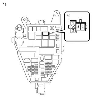
*1 No. 1 Engine Room Relay Block and Junction Block Assembly *2 IG2 NO. 2 Relay Remove the IG2 NO. 2 relay from the No. 1 engine room relay block and junction block assembly.
-
Measure the voltage according to the value(s) in the table below.
Standard Voltage Tester Connection Condition Specified Condition 3 (IG2 NO. 2 relay) - Body ground Always 11 to 14 V Result Proceed to OK NG
NG
REPAIR OR REPLACE HARNESS OR CONNECTOR (IG2 NO. 2 RELAY - AUXILIARY BATTERY)
OK
-
-
CHECK HARNESS AND CONNECTOR (IG2 NO. 2 RELAY - BODY GROUND)
-
Remove the IG2 NO. 2 relay from the No. 1 engine room relay block and junction block assembly.
-
Measure the resistance according to the value(s) in the table below.
Standard Resistance Tester Connection Condition Specified Condition 1 (IG2 NO. 2 relay) - Body ground Always Below 1 Ω Result Proceed to OK NG
OK
GO TO ENTRY AND START SYSTEM (FOR START FUNCTION) Click here
NG
REPAIR OR REPLACE HARNESS OR CONNECTOR
-