SFI SYSTEM(w/ Canister Pump Module), Diagnostic DTC:P001313, P002313
| DTC Code | DTC Name |
|---|---|
| P001313 | Camshaft Position "B" - Actuator Bank 1 Circuit Open |
| P002313 | Camshaft Position "B" - Actuator Bank 2 Circuit Open |
DESCRIPTION
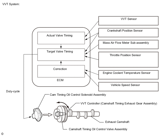
The Variable Valve Timing (VVT) system adjusts the exhaust valve timing to improve driveability. The engine oil pressure turns the VVT controller to adjust the valve timing.
The cam timing oil control solenoid assembly operates according to signals received from the ECM to control the position of the camshaft timing oil control valve assembly and supply engine oil. The camshaft timing oil control valve assembly moves when the ECM applies 12 V to the cam timing oil control solenoid assembly. The ECM changes the energizing time of the cam timing oil control solenoid assembly (duty-cycle) in accordance with the camshaft position, crankshaft position, throttle position, etc.
| DTC No. | Detection Item | DTC Detection Condition | Trouble Area | MIL | Memory | Note |
|---|---|---|---|---|---|---|
| P001313 | Camshaft Position "B" - Actuator Bank 1 Circuit Open | Open or short in cam timing oil control solenoid assembly (for exhaust camshaft of bank 1) circuit (1 trip detection logic). |
|
Comes on | DTC stored | SAE: P0013 |
| P002313 | Camshaft Position "B" - Actuator Bank 2 Circuit Open | Open or short in cam timing oil control solenoid assembly (for exhaust camshaft of bank 2) circuit (1 trip detection logic). |
|
Comes on | DTC stored | SAE: P0023 |
MONITOR DESCRIPTION
These DTCs are designed to detect an open or short in the cam timing oil control solenoid assembly (for exhaust camshaft) circuit. If the cam timing oil control solenoid duty-cycle is excessively high or low while the power switch is on (IG) or the engine is running, the ECM will illuminate the MIL and store this DTC.
MONITOR STRATEGY
| Required Sensors/Components | Cam timing oil control solenoid assembly (for exhaust camshaft) |
| Frequency of Operation | Continuous |
CONFIRMATION DRIVING PATTERN
-
Connect the GTS to the DLC3.
-
Turn the power switch is on (IG) and turn the GTS on.
-
Clear the DTCs (even if no DTCs are stored, perform the clear DTC procedure).
-
Turn the power switch off and wait for at least 30 seconds.
-
Turn the power switch is on (IG) and turn the GTS on.
-
With power switch on (IG) and wait for 5 seconds or more.
-
Enter the following menus: Powertrain / Engine / Trouble Codes.
-
Read the pending DTCs.
Tech Tips
-
If a pending DTC is output, the system is malfunctioning.
-
If a pending DTC is not output, perform the following procedure.
-
-
Enter the following menus: Powertrain / Engine / Utility / All Readiness.
-
Input the DTC: P001313 or P002313.
-
Check the DTC judgment result.
GTS Display Description NORMAL
-
DTC judgment completed
-
System normal
ABNORMAL
-
DTC judgment completed
-
System abnormal
INCOMPLETE
-
DTC judgment not completed
-
Perform driving pattern after confirming DTC enabling conditions
Tech Tips
-
If the judgment result shows NORMAL, the system is normal.
-
If the judgment result shows ABNORMAL, the system has a malfunction.
-
WIRING DIAGRAM
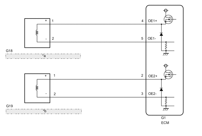
| *a | Cam Timing Oil Control Solenoid Assembly (for Exhaust Camshaft of Bank 1) |
| *b | Cam Timing Oil Control Solenoid Assembly (for Exhaust Camshaft of Bank 2) |
CAUTION / NOTICE / HINT
Note
-
Vehicle Control History may be stored in the hybrid vehicle control ECU if the engine is malfunctioning. Certain vehicle condition information is recorded when Vehicle Control History is stored. Reading the vehicle conditions recorded in both the freeze frame data and Vehicle Control History can be useful for troubleshooting.
(Select Powertrain in Health Check and then check the time stamp data.)
-
If any "Engine Malfunction" Vehicle Control History item has been stored in the hybrid vehicle control ECU, make sure to clear it. However, as all Vehicle Control History items are cleared simultaneously, if any Vehicle Control History items other than "Engine Malfunction" are stored, make sure to perform any troubleshooting for them before clearing Vehicle Control History.
Tech Tips
-
If DTC P001313 is output, check the VVT system (for exhaust camshaft of bank 1) circuit.
-
If DTC P002313 is output, check the VVT system (for exhaust camshaft of bank 2) circuit.
-
Bank 1 refers to the bank that includes the No. 1 cylinder*.
*: The No. 1 cylinder is the cylinder which is farthest from the transmission
-
Bank 2 refers to the bank that does not include the No. 1 cylinder.
-
Read freeze frame data using the GTS. The ECM records vehicle and driving condition information as freeze frame data the moment a DTC is stored. When troubleshooting, freeze frame data can help determine if the vehicle was moving or stationary, if the engine was warmed up or not, if the air fuel ratio was lean or rich, and other data from the time the malfunction occurred.
PROCEDURE
-
CLEAR DTC
-
Connect the GTS to the DLC3.
-
Turn the power switch on (IG).
-
Turn the GTS on.
-
Clear the DTC after recording the freeze frame data and DTC.
Powertrain > Engine > Clear DTCs -
Turn the power switch off and wait for at least 30 seconds.
Result Proceed to NEXT
NEXT 
-
-
READ DTC OUTPUT (DTC P001313 OR P002313)
-
Connect the GTS to the DLC3.
-
Turn the power switch on (IG).
-
Turn the GTS on.
-
Turn the power switch on (IG) and wait 5 seconds.
-
Turn the GTS on.
-
Enter the following menus: Powertrain / Engine / Trouble Codes.
-
Read the DTCs.
Powertrain > Engine > Clear DTCsResult Result Proceed to DTC P001313 or P002313 is output A DTCs are not output B
B 
CHECK FOR INTERMITTENT PROBLEMS Click here
A
-
-
INSPECT CAM TIMING OIL CONTROL SOLENOID ASSEMBLY (FOR EXHAUST CAMSHAFT)
-
Inspect the cam timing oil control solenoid assembly (for exhaust camshaft).
for Bank 1: Click here
for Bank 2: Click here
Result Proceed to OK NG
NG
REPLACE CAM TIMING OIL CONTROL SOLENOID ASSEMBLY (FOR EXHAUST CAMSHAFT) for Bank 1: Click here
REPLACE CAM TIMING OIL CONTROL SOLENOID ASSEMBLY (FOR EXHAUST CAMSHAFT) for Bank 2: Click hereOK
-
-
CHECK HARNESS AND CONNECTOR (CAM TIMING OIL CONTROL SOLENOID ASSEMBLY (FOR EXHAUST CAMSHAFT) - ECM)
-
Disconnect the cam timing oil control solenoid assembly (for exhaust camshaft) connector.
-
Disconnect the ECM connector.
-
Measure the resistance according to the value(s) in the table below.
Standard Resistance Tester Connection Condition Specified Condition G18-1 (+) - G1-4 (OE1+) Always Below 1 Ω G18-2 (-) - G1-5 (OE1-) Always Below 1 Ω G19-1 (+) - G1-2 (OE2+) Always Below 1 Ω G19-2 (-) - G1-3 (OE2-) Always Below 1 Ω G18-1 (+) or G1-4 (OE1+) - Body ground and other terminals Always 10 kΩ or higher G18-2 (-) or G1-5 (OE1-) - Body ground and other terminals Always 10 kΩ or higher G19-1 (+) or G1-2 (OE2+) - Body ground and other terminals Always 10 kΩ or higher G19-2 (-) or G1-3 (OE2-) - Body ground and other terminals Always 10 kΩ or higher Result Proceed to OK NG
OK
REPLACE ECM Click here
NG
REPAIR OR REPLACE HARNESS OR CONNECTOR
-