NAVIGATION SYSTEM, Diagnostic DTC:B1579
| DTC Code | DTC Name |
|---|---|
| B1579 | Voice Recognition Microphone Disconnected |
DESCRIPTION
The radio receiver assembly and telephone microphone assembly are connected to each other using the microphone connection detection signal lines.
This DTC is stored when a microphone connection detection signal line is disconnected.
| DTC No. | Detection Item | DTC Detection Condition | Trouble Area |
|---|---|---|---|
| B1579 | Voice Recognition Microphone Disconnected | Telephone microphone signal is lost. |
|
WIRING DIAGRAM
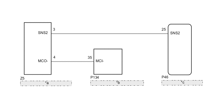
| *a | Telephone Microphone Assembly |
| *b | Telephone Transceiver Assembly |
| *c | Radio Receiver Assembly |
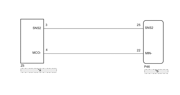
| *a | Telephone Microphone Assembly |
| *b | Radio Receiver Assembly |
CAUTION / NOTICE / HINT
Note
-
The following malfunctions may occur if a radio receiver assembly from another vehicle is installed to this vehicle. Therefore, when replacing the radio receiver assembly, be sure to replace it with new one.
-
Communication malfunction DTC is output
-
Does not operate normally
-
When replacing the telephone transceiver assembly, make sure to replace it with a new one (w/ Telematics Transceiver).
Tech Tips
Depending on the parts that are replaced during vehicle inspection or maintenance, performing initialization, registration or calibration may be needed. Refer to Precaution for Navigation System.
PROCEDURE
-
CHECK VEHICLE TYPE
-
Check the vehicle type.
Result Result Proceed to w/ Telematics Transceiver A w/o Telematics Transceiver B
B 
CHECK HARNESS AND CONNECTOR (RADIO RECEIVER ASSEMBLY - TELEPHONE MICROPHONE ASSEMBLY) Click here
A 
-
-
CHECK HARNESS AND CONNECTOR (RADIO RECEIVER ASSEMBLY - TELEPHONE MICROPHONE ASSEMBLY)
-
Disconnect the P46 radio receiver assembly connector.
-
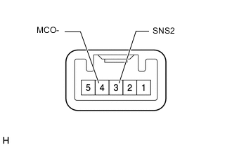
Disconnect the Z5 telephone microphone assembly connector.
-
Measure the resistance according to the value(s) in the table below.
Standard Resistance Tester Connection Condition Specified Condition P46-25 (SNS2) - Z5-3 (SNS2) Always Below 1 Ω P46-25 (SNS2) - Body ground Always 10 kΩ or higher Result Proceed to OK NG
NG 
REPAIR OR REPLACE HARNESS OR CONNECTOR
OK
-
-
CHECK HARNESS AND CONNECTOR (TELEPHONE TRANSCEIVER ASSEMBLY - TELEPHONE MICROPHONE ASSEMBLY)
-
Disconnect the P134 telephone transceiver assembly connector.
-
Disconnect the Z5 telephone microphone assembly connector.
-
Measure the resistance according to the value(s) in the table below.
Standard Resistance Tester Connection Condition Specified Condition P134-35 (MCI-) - Z5-4 (MCO-) Always Below 1 Ω P134-35 (MCI-) - Body ground Always 10 kΩ or higher Result Proceed to OK NG
NG
REPAIR OR REPLACE HARNESS OR CONNECTOR
OK
-
-
CHECK TELEPHONE TRANSCEIVER ASSEMBLY (MCI-)
-
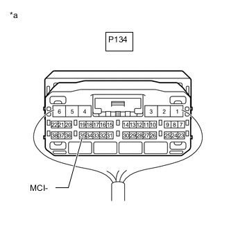
*a Component with harness connected
(Telephone Transceiver Assembly)
Remove the telephone transceiver assembly with the connector(s) still connected.
-
Measure the resistance according to the value(s) in the table below.
Standard Resistance Tester Connection Condition Specified Condition P134-35 (MCI-) - Body ground Always Below 1 Ω Result Proceed to OK NG
NG
REPLACE TELEPHONE TRANSCEIVER ASSEMBLY Click here
OK
-
-
INSPECT TELEPHONE MICROPHONE ASSEMBLY (SNS2, MCO-)
-
Remove the telephone microphone assembly.
-
Measure the resistance according to the value(s) in the table below.
Standard Resistance Tester Connection Condition Specified Condition 3 (SNS2) - 4 (MCO-) Always Below 1 Ω Result Proceed to OK NG
OK
REPLACE RADIO RECEIVER ASSEMBLY Click here
NG
REPLACE TELEPHONE MICROPHONE ASSEMBLY Click here
-
-
CHECK HARNESS AND CONNECTOR (RADIO RECEIVER ASSEMBLY - TELEPHONE MICROPHONE ASSEMBLY)
-
Disconnect the P46 radio receiver assembly connector.
-
Disconnect the Z5 telephone microphone assembly connector.
-
Measure the resistance according to the value(s) in the table below.
Standard Resistance Tester Connection Condition Specified Condition P46-25 (SNS2) - Z5-3 (SNS2) Always Below 1 Ω P46-22 (MIN-) - Z5-4 (MCO-) Always Below 1 Ω P46-25 (SNS2) - Body ground Always 10 kΩ or higher P46-22 (MIN-) - Body ground Always 10 kΩ or higher Result Proceed to OK NG
NG
REPAIR OR REPLACE HARNESS OR CONNECTOR
OK
-
-
INSPECT TELEPHONE MICROPHONE ASSEMBLY (SNS2, MCO-)
-
Remove the telephone microphone assembly.
-
Measure the resistance according to the value(s) in the table below.
Standard Resistance Tester Connection Condition Specified Condition 3 (SNS2) - 4 (MCO-) Always Below 1 Ω Result Proceed to OK NG
OK
REPLACE RADIO RECEIVER ASSEMBLY Click here
NG
REPLACE TELEPHONE MICROPHONE ASSEMBLY Click here
-