NAVIGATION SYSTEM TERMINALS OF ECU
-
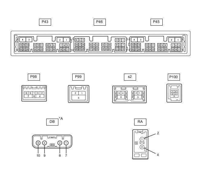
*A w/ DAB Function - - Terminal No. (Symbol) Wiring Color Terminal Description Condition Specified Condition P43-1 (GND1) - Body ground W-B - Body ground Ground Always Below 1 Ω P43-2 (GND2) - Body ground SB - Body ground Ground Always Below 1 Ω P43-3 (+B) - P43-1 (GND1) G - W-B Power source (+B) Power switch off 11 to 14 V P43-4 (+B1) - P43-1 (GND1) LA-R - W-B Power source (+B) Power switch off 11 to 14 V P43-5 (TX1+) B AVC-LAN communication signal - - P43-6 (TX1-) W AVC-LAN communication signal - - P43-10 (AGND) - P43-1 (GND1) Shielded - W-B Shield ground Always Below 1 Ω P43-11 (VAL+) - P43-13 (VA-) B - R Sound signal (Left) External device system playing (when No. 1 stereo jack adapter assembly used) A waveform synchronized with sound signals is output P43-12 (VAR+) - P43-13 (VA-) W - R Sound signal (Right) External device system playing (when No. 1 stereo jack adapter assembly used) A waveform synchronized with sound signals is output P43-13 (VA-) - P43-1 (GND1) R - W-B Sound signal ground Always Below 1 Ω P43-14 (ADPG) - P43-13 (VA-) V - R External device connection detection signal External device connected 1.3 to 1.8 V External device not connected 2.2 to 3.3 V P43-15 (ACC1) - P43-1 (GND1) P - W-B Power source (ACC) Power switch on (ACC) 11 to 14 V Power switch off Below 1 V P43-16 (ACC) - P43-1 (GND1) BE - W-B Power source (ACC) Power switch on (ACC) 11 to 14 V Power switch off Below 1 V P43-21 (SW1) - P43-24 (SWG) L - BR Steering pad switch signal No switch pushed 2.97 to 3.56 V Seek+ switch pushed 0.27 to 0.35 V Seek- switch pushed 0.86 to 1.03 V Vol+ switch pushed 1.51 to 1.79 V Vol- switch pushed 2.22 to 2.66 V P43-22 (SW2) - P43-24 (SWG) P - BR Steering pad switch signal No switch pushed 2.97 to 3.56 V MODE switch pushed 0.27 to 0.35 V TEL switch pushed 1.51 to 1.79 V Voice switch pushed 2.22 to 2.66 V P43-24 (SWG) - Body ground BR - Body ground Steering pad switch signal Always Below 1 Ω P43-27 (SPD) - P43-1 (GND1) B - W-B Vehicle speed signal See "Vehicle Signal Check Mode" in Operation Check
- P45-7 (SUP) - P43-1 (GND1) V - W-B Start up signal 20 seconds elapse after turning the power switch on (ACC) 11 to 14 V P45-10 (USBV) - P43-1 (GND1)*1 LG - W-B Telephone transceiver assembly power supply Power switch off Below 1 V Power switch on (ACC) 4.75 to 5.25 V P45-11 (USBG) - Body ground*1 SB - W-B Ground Always Below 1 Ω P45-12 (SGND) - Body ground*1 Shielded - Body ground Shield ground Always Below 1 Ω P45-13 (VOR+) - P43-1 (GND1)*1 G - W-B Receive voice signal Destination assist service in use and operator speaking to vehicle occupant A waveform synchronized with the received voice is output. P45-14 (VOR-) - P43-1 (GND1)*1 L - W-B Receive voice signal Destination assist service in use and operator speaking to vehicle occupant A waveform synchronized with the received voice is output. P45-15 (VOT+) - P43-1 (GND1)*1 R - W-B Sent voice signal Destination assist service in use and vehicle occupant speaking to operator A waveform synchronized with the sent voice is output. P45-16 (VOT-) - P43-1 (GND1)*1 W - W-B Sent voice signal Destination assist service in use and vehicle occupant speaking to operator A waveform synchronized with the sent voice is output. P45-19 (RST)*2 P - - - P45-22 (SI+) - P43-1 (GND1) R - W-B Voice signal Voice guidance sounding A waveform synchronized with sound is output P45-23 (SI-) - P43-1 (GND1) G - W-B Voice signal Voice guidance sounding A waveform synchronized with sound is output P45-24 (SGND) - P43-1 (GND1) Shielded - W-B Shield ground Always Below 1 Ω P45-25 (MCO+) - P45-26 (MCO-) B - W Microphone voice signal See "Check Microphone (DCU)" in Operation Check
- P45-26 (MCO-) - P43-1 (GND1) W - W-B Microphone voice signal See "Check Microphone (DCU)" in Operation Check
- P45-28 (REV2) - P43-1 (GND1) L - W-B Reverse signal Power switch on (READY), shift position not in R → in R 2 V or less → 11 to 14 V P46-1 (VMTF) - P43-1 (GND1) P - W-B Visual mute signal Power switch on(ACC) Screen display changing 3.5 V or higher → Below 1 V → 3.5 V or higher P46-5 (CNH1) Y Local bus communication signal - - P46-6 (CNL1) W Local bus communication signal - - P46-13 (CANH) L CAN communication signal - - P46-14 (CANL) LG CAN communication signal - - P46-15 (ILL+) - P43-1 (GND1) P - W-B Illumination signal Power switch on (IG), light control switch off → tail or head position Below 1 V → 11 to 14 V P46-16 (ILL-) - P43-1 (GND1) GR - W-B Illumination signal Power switch on (IG), light control switch off → tail or head position (Light intensity is not max or min.) Below 1 V → Pulse generation P46-19 (IG) - P43-1 (GND1) G - W-B Power source (IG) Power switch off Below 1 V Power switch on (IG) 11 to 14 V P46-21 (MIN+) - P43-1 (GND1) W - W-B Microphone voice signal See "Check Microphone" in Operation Check
- P46-22 (MIN-) - P43-1 (GND1) B - W-B Microphone voice signal See "Check Microphone" in Operation Check
- P46-23 (MACC) - P43-1 (GND1)*3 R - W-B Telephone microphone assembly power supply Power switch off Below 1 V Power switch on (ACC) 4 to 6 V P46-24 (SGND) - Body ground Shielded - Body ground Shield ground Always Below 1 Ω P46-25 (SNS2) - P43-1 (GND1) L - W-B Microphone connection detection signal Always Below 1 V P98-1 (WUO) W MOST communication signal Power switch on (ACC) 4.5 V or higher Power switch off Below 1 V P98-2 (MI+) # MOST communication signal - - P98-3 (MI-) # MOST communication signal - - P98-4 (SLDI) - P43-1 (GND1) Shielded - W-B Shield ground Always Below 1 Ω P98-5 (MO+) # MOST communication signal - - P98-6 (MO-) # MOST communication signal - - P98-7 (SLDO) - P43-1 (GND1) Shielded - W-B Shield ground Always Below 1 Ω P99-1 (GVIF-) # Video signal (Digital) - - P99-2 (GVIF+) # Video signal (Digital) - - P99-3 (GND) - Body ground Shielded - Body ground Shield ground Always Below 1 Ω P100-1 (USV1) # Power source - - P100-2 (US1-) # Data signal - - P100-3 (US1+) # Data signal - - P100-4 (UGD1) # Ground - - P100-5 (USG1) - Body ground Shielded - Body ground Shield ground Always Below 1 Ω s2-1 (GVIF-) # Video signal (Digital) - - s2-2 (GVIF+) # Video signal (Digital) - - s2-3 (GND) - Body ground Shielded - Body ground Shield ground Always Below 1 Ω s2-4 (USB+) # USB communication line - - s2-5 (USB-) # USB communication line - - s2-6 (USBS) - Body ground Shielded - Body ground Shield ground Always Below 1 Ω RA-5 - P43-1 (GND1) # - W-B Power source of antenna Power switch on (ACC)
Radio switch on and AM or FM selected
11 to 14 V *1: w/ Telematics Transceiver
*2: It is connected, but not used
*3: w/o Telematics Transceiver
#: There is no wire color information
RADIO RECEIVER ASSEMBLY
-
NAVIGATION ECU
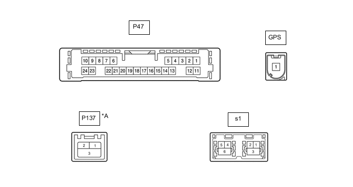
*A w/ Telematics Transceiver - - Terminal No. (Symbol) Wiring Color Terminal Description Condition Specified Condition P47-6 (VOI+) - P47-23 (GND) R - W-B Voice signal Voice guidance sounding A waveform synchronized with sound is output P47-7 (VOI-) - P47-23 (GND) G - W-B Voice signal Voice guidance sounding A waveform synchronized with sound is output P47-8 (SLD1) - Body ground Shielded - Body ground Shield ground Always Below 1 Ω P47-9 (SPD) - P47-23 (GND) SB - W-B Vehicle speed signal See "Check GPS and Vehicle Sensors" in Operation Check
- P47-10 (+B) - P47-23 (GND) G - W-B Power source (+B) Power switch off 11 to 14 V P47-13 (MIC+) - P47-23 (GND) B - W-B Microphone voice signal See "Microphone Check (MEU)" in Operation Check
- P47-14 (MIC-) - Body ground W - Body ground Microphone voice signal See "Microphone Check (MEU)" in Operation Check
- P47-19 (REV2) - P47-23(GND) L - W-B Reverse signal Power switch on (READY), shift position not in R → in R 2 V or less → 11 to 14 V P47-21 (SUP) - P47-23 (GND) V - W-B Power source (ACC) 20 seconds elapse after turning the power switch on (ACC) 11 to 14 V P47-22 (RST)*1 P - - - P47-23 (GND) - Body ground W-B - Body ground Ground Always Below 1 Ω P137-1 (USB+)*2 GR USB communication line - - P137-2 (USB-)*2 GR USB communication line - - P137-3 (USBS) - Body ground*2 GR - Body ground Shield ground Always Below 1 Ω s1-1 (GVIF-) # Video signal (Digital) - - s1-2 (GVIF+) # Video signal (Digital) - - s1-3 (GND) - Body ground Shielded - Body ground Shield ground Always Below 1 Ω s1-4 (USB+) # USB communication line - - s1-5 (USB-) # USB communication line - - s1-6 (USBS) - Body ground Shielded - Body ground Shield ground Always Below 1 Ω *1: It is connected, but not used
*2: w/ Telematics Transceiver
#: There is no wire color information
-
STEREO COMPONENT AMPLIFIER ASSEMBLY
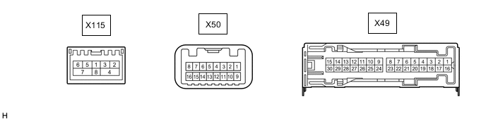
Terminal No. (Symbol) Wiring Color Terminal Description Condition Specified Condition X49-1 (+B) - X49-3 (GND) SB - W-B Power source (+B) Power switch off 11 to 14 V X49-2 (TMUT) - Body ground*1 W - Body ground Mute signal Audio system playing 3.0 to 5.0 V Emergency call mode Below 1 V X49-3 (GND) - Body ground W-B - Body ground Ground Always Below 1 V X49-4 (WFL+) - X49-3 (GND) LA-SB - W-B Sound signal (Front Left) Audio system playing A waveform synchronized with sound signals is output X49-5 (WFR+) - X49-3 (GND) LA-W - W-B Sound signal (Front Right) Audio system playing A waveform synchronized with sound signals is output X49-6 (WF1+) - X49-3 (GND) GR - W-B Sound signal (Woofer) Audio system playing A waveform synchronized with sound signals is output X49-7 (CTR+) - X49-3 (GND) LA-G - W-B Sound signal (Front Center) Audio system playing A waveform synchronized with sound signals is output X49-8 (SL+) - X49-3 (GND) LA-V - W-B Sound signal (Rear Left) Audio system playing A waveform synchronized with sound signals is output X49-9 (SR+) - X49-3 (GND) LA-SB - W-B Sound signal (Rear Right) Audio system playing A waveform synchronized with sound signals is output X49-10 (MR+) - X49-3 (GND)*2 LA-W - W-B Sound signal (Front Center) Audio system playing A waveform synchronized with sound signals is output X49-11 (TWL+) - X49-3 (GND)*2 LA-GR - W-B Sound signal (Front Left) Audio system playing A waveform synchronized with sound signals is output X49-12 (FL+) - X49-3 (GND) LA-G - W-B Sound signal (Front Left) Audio system playing A waveform synchronized with sound signals is output X49-13 (FR+) - X49-3 (GND) LA-V - W-B Sound signal (Front Right) Audio system playing A waveform synchronized with sound signals is output X49-14 (TWR+) - X49-3 (GND)*2 LA-B - W-B Sound signal (Front Right) Audio system playing A waveform synchronized with sound signals is output X49-16 (+B2) - X49-3 (GND) BE - W-B Power source (+B) Power switch off 11 to 14 V X49-17 (SPD) - X49-3 (GND) P - W-B Vehicle speed signal Power switch on (IG)
Wheel being rotated
Pulse generation X49-18 (GND2) - Body ground W-B - Body ground Ground Always Below 1 Ω X49-19 (WFL-) - X49-3 (GND) LA-L - W-B Sound signal (Front Left) Audio system playing A waveform synchronized with sound signals is output X49-20 (WFR-) - X49-3 (GND) LA-L - W-B Sound signal (Front Right) Audio system playing A waveform synchronized with sound signals is output X49-21 (WF1-) - X49-3 (GND) L - W-B Sound signal (Woofer) Audio system playing A waveform synchronized with sound signals is output X49-22 (CTR-) - X49-3 (GND) LA-L - W-B Sound signal (Front Center) Audio system playing A waveform synchronized with sound signals is output X49-23 (SL-) - X49-3 (GND) LA-L - W-B Sound signal (Rear Left) Audio system playing A waveform synchronized with sound signals is output X49-24 (SR-) - X49-3 (GND) LA-R - W-B Sound signal (Rear Right) Audio system playing A waveform synchronized with sound signals is output X49-25 (MR-) - X49-3 (GND)*2 LA-R - W-B Sound signal (Front Center) Audio system playing A waveform synchronized with sound signals is output X49-26 (TWL-) - X49-3 (GND)*2 LA-SB - W-B Sound signal (Front Left) Audio system playing A waveform synchronized with sound signals is output X49-27 (FL-) - X49-3 (GND) LA-R - W-B Sound signal (Front Left) Audio system playing A waveform synchronized with sound signals is output X49-28 (FR-) - X49-3 (GND) LA-L - W-B Sound signal (Front Right) Audio system playing A waveform synchronized with sound signals is output X49-29 (TWR-) - X49-3 (GND)*2 LA-BE - W-B Sound signal (Front Right) Audio system playing A waveform synchronized with sound signals is output X115-2 (MI+) # MOST communication signal - - X115-3 (MI-) # MOST communication signal - - X115-4 (SLDI) Shielded Shield ground - - X115-5 (MO+) # MOST communication signal - - X115-6 (MO-) # MOST communication signal - - X115-7 (SLDO) Shielded Shield ground - - X115-8 (WUI) W MOST communication wake-up signal - - X50-2 (ACK1) GR Serial communication (UART) signal - - X50-3 (ACNT) B Active noise control system control signal Active noise control system operating Below 1 V Active noise control system not operating 4.5 V or higher X50-6 (AN3+) G Active noise control microphone input signal Active noise control system operating Pulse generation X50-7 (AN2+) R Active noise control microphone input signal Active noise control system operating Pulse generation X50-8 (AN1+) W Active noise control microphone input signal Active noise control system operating Pulse generation X50-10 (ACK2) V Serial communication (UART) signal - - X50-14 (AN3-) GR Active noise control microphone input signal Active noise control system operating Pulse generation X50-15 (AN2-) L Active noise control microphone input signal Active noise control system operating Pulse generation X50-16 (AN1-) B Active noise control microphone input signal Active noise control system operating Pulse generation *1: w/ Telematics Transceiver
*2: for 13 Speakers
#: There is no wire color information
-
MULTI-DISPLAY

Terminal No. (Symbol) Wiring Color Terminal Description Condition Specified Condition P42-2 (ILL) - P42-13 (GND1) LA-L - W-B Illumination signal Power switch on (IG), light control switch off → tail or head position Below 1 V → 11 to 14 V P42-3 (REV) - P42-13(GND1) LA-R - W-B Reverse signal Power switch on (READY), shift position not in R → in R 2 V or less → 11 to 14 V P42-6 (TX1+) R AVC-LAN communication signal - - P42-7 (TX+) B AVC-LAN communication signal - - P42-8 (V+) - P42-9 (V-) R - W Video signal Power switch on (READY)
Shift position in R
Camera lens not covered, displaying image
Pulse generation
(Refer to waveform 1)
Power switch on (READY)
Shift position in R
Camera lens covered, blacking out screen
Pulse generation
(Refer to waveform 2)
P42-9 (V-) - Body ground W - Body ground Video signal ground Always Below 1 Ω P42-10 (CA+) - P42-21 (CGND) B - G Power source Power switch on (ACC) 5.5 to 7.05 V P42-11 (VMTI) - P42-13 (GND1) P - W-B Visual mute signal When image on display switches 3.5 V or higher → Below 1 V → 3.5 V or higher P42-12 (B) - P42-13 (GND1) V - W-B Power source (+B) Power switch off 11 to 14 V P42-13 (GND1) - Body ground W-B - Body ground Ground Always Below 1 Ω P42-18 (TX1-) L AVC-LAN communication signal - - P42-19 (TX-) W AVC-LAN communication signal - - P42-20 (CSLD) - Body ground Shielded - Body ground Shield ground Always Below 1 Ω P42-21 (CGND) - Body ground G - Body ground Camera ground Always Below 1 Ω P42-24 (ACC) - P42-13 (GND1) LA-SB - W-B Power source (ACC) Power switch on (ACC) 11 to 14 V Power switch off Below 1 V P101-1 (GVIF+) # Video signal (Digital) - - P101-2 (GVIF-) # Video signal (Digital) - - P101-3 (GND) Shielded Shield ground - - #: There is no wire color information
-
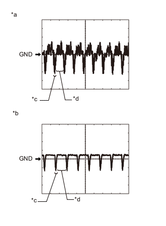
*a Waveform 1 (camera lens not covered, displaying image) *b Waveform 2 (camera lens covered, blacking out screen) *c Synchronization Signal *d Video Waveform Reference (Oscilloscope waveform):
-
Waveform 1 (camera lens is not covered, displaying an image)
Item Content Measurement terminal P42-8 (V+) - P42-9 (V-) Measurement setting 200 mV/DIV., 50 μs./DIV. Condition Power switch on (READY), shift position in R, camera lens not covered, displaying image Tech Tips
-
The video waveform changes according to the image sent by the television camera assembly.
-
The video waveform is constantly output when the power switch is on (ACC).
-
-
Waveform 2 (camera lens is covered, blacking out the screen)
Item Content Measurement terminal P42-8 (V+) - P42-9 (V-) Measurement setting 200 mV/DIV., 50 μs./DIV. Condition Power switch on (READY), shift position in R, camera lens covered, blacking out screen Tech Tips
-
The video waveform changes according to the image sent by the television camera assembly.
-
The video waveform is constantly output when the power switch is on (ACC).
-
-
-
-
SWITCH AND VOLUME ASSEMBLY

Terminal No. (Symbol) Wiring Color Terminal Description Condition Specified Condition P86-1 (ACC) - P86-3 (GND) LA-G - W-B Power source (ACC) Power switch on (ACC) 11 to 14 V Power switch off Below 1 V P86-3 (GND) - Body ground W-B - Body ground Ground Always Below 1 Ω P86-4 (TX+) R AVC-LAN communication signal - - P86-6 (ILL+) - P86-3 (GND) LA-B - W-B Illumination signal Power switch on (IG), light control switch off → tail or head position Below 1 V → 11 to 14 V P86-7 (ILL-) - Body ground LA-BE - Body ground Illumination signal Power switch on (IG), light control switch off → tail or head position (Light intensity is not max or min.) Below 1 V → Pulse generation P86-8 (TX-) L AVC-LAN communication signal - - -
REMOTE OPERATION CONTROLLER ASSEMBLY (REMOTE TOUCH)

Terminal No. (Symbol) Wiring Color Terminal Description Condition Specified Condition P69-1 (+B) - P69-10 (GND) LA-P - W-B Power source (+B) Power switch off 11 to 14 V P69-6 (ACC) - P69-10 (GND) LA-V - W-B Power source (ACC) Power switch on (ACC) 11 to 14 V Power switch off Below 1 V P69-8 (MO-) W Local bus communication signal - - P69-9 (MO+) G Local bus communication signal - - P69-2 (ILL+) - P69-10 (GND) LA-L - W-B Illumination signal Power switch on (IG), light control switch off → tail or head position Below 1 V → 11 to 14 V P69-10 (GND) - Body ground W-B - Body ground Ground Always Below 1 Ω P69-5 (ILL-) - P69-10 (GND) LA-BE - W-B Illumination signal Power switch on (IG), light control switch off → tail or head position (Light intensity is not max or min.) Below 1 V → Pulse generation -
CHECK TELEPHONE TRANSCEIVER ASSEMBLY (w/ Telematics Transceiver)
-
CHECK STEREO COMPONENT EQUALIZER ASSEMBLY
-
CLOCK ASSEMBLY