RADIO RECEIVER REMOVAL
CAUTION / NOTICE / HINT
The necessary procedures (adjustment, calibration, initialization, or registration) that must be performed after parts are removed, installed, or replaced during the radio receiver removal/installation are shown below.
| Replacement part or procedure | Necessary procedures | Effects/Inoperative when not performed | Link |
|---|---|---|---|
| Disconnect cable from negative auxiliary battery terminal | Memorize steering angle neutral point | LKA/LDA system | |
| Pre-collision system | |||
| Parking assist monitor system | |||
| Steering sensor zero point calibration | Variable gear ratio steering system | ||
| Radio receiver assembly | Re-install the eOwner's manual | The eOwner's manual cannot be used | - |
| Download necessary data | G-BOOK function |
Note
After the power switch is turned off, the radio receiver assembly records various types of memory and settings. As a result, after turning the power switch off, be sure to wait for the time specified in the following table before disconnecting the cable from the negative (-) auxiliary battery terminal.
| System Name | See Procedure |
|---|---|
| Vehicle enrolled in telematics system (for G-BOOK) | 6 minutes |
| Vehicle not enrolled in telematics system (for G-BOOK) | 1 minute |
Tech Tips
-
Use the same procedure as for the RHD and LHD vehicles.
-
The procedure listed below is for the LHD vehicles.
PROCEDURE
-
PRECAUTION
Note
-
After turning the power switch off, waiting time may be required before disconnecting the cable from the negative (-) auxiliary battery terminal. Therefore, make sure to read the disconnecting the cable from the negative (-) auxiliary battery terminal notices before proceeding with work.
-
After replacing the radio receiver assembly, if the "New software is not compatible with the system. Contact your dealer." on-screen message is displayed on the multi-display, update the software of the navigation ECU.
-
-
REMOVE NO. 2 DECK BOARD
-
DISCONNECT CABLE FROM NEGATIVE AUXILIARY BATTERY TERMINAL
Note
When disconnecting the cable, some systems need to be initialized after the cable is reconnected.
-
REMOVE INTEGRATION CONTROL AND PANEL ASSEMBLY
-
REMOVE RADIO RECEIVER ASSEMBLY WITH BRACKET
-
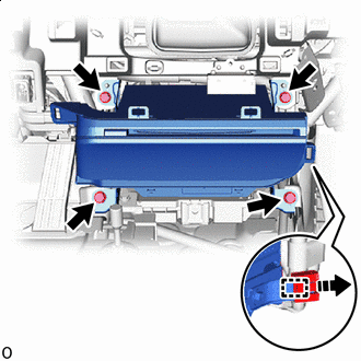

Remove in this Direction Remove the 4 bolts.
-
Pull out the radio receiver assembly with bracket.
-
Detach the clamp as indicated by the arrows in the shown in the illustration.
-
Disconnect the connectors and remove the radio receiver assembly with bracket.
-
-
REMOVE NO. 1 NAVIGATION WIRE
-
REMOVE NO. 1 RADIO BRACKET
-
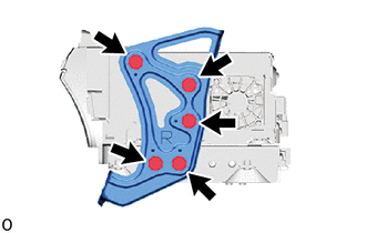
Remove the 5 screws and No. 1 radio bracket.
-
-
REMOVE NO. 2 RADIO BRACKET
-
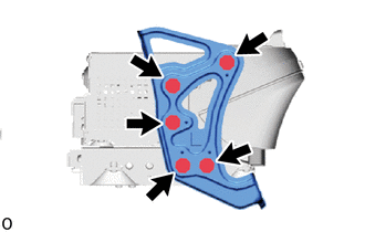
Remove the 5 screws and No. 2 radio bracket.
-
-
REMOVE RADIO RECEIVER ASSEMBLY