AUDIO AND VISUAL SYSTEM Stereo Jack Adapter Light does not Illuminate
DESCRIPTION
Power is supplied to the No. 1 stereo jack adapter assembly illumination from the radio receiver assembly.
WIRING DIAGRAM
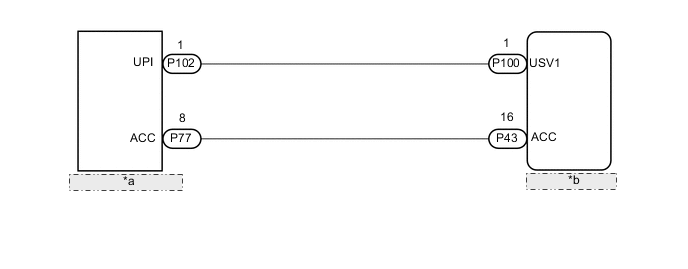
| *a | No. 1 Stereo Jack Adapter Assembly |
| *b | Radio Receiver Assembly |
CAUTION / NOTICE / HINT
Note
The following malfunctions may occur if a radio receiver assembly from another vehicle is installed to this vehicle. Therefore, when replacing the radio receiver assembly, be sure to replace it with new one.
-
Communication malfunction DTC is output
-
Does not operate normally
Tech Tips
Depending on the parts that are replaced during vehicle inspection or maintenance, performing initialization, registration or calibration may be needed. Refer to Precaution for Audio and Visual System.
PROCEDURE
-
CHECK HARNESS AND CONNECTOR (NO. 1 STEREO JACK ADAPTER ASSEMBLY ILLUMINATION POWER SOURCE)
-
Disconnect the P102 and P77 No. 1 stereo jack adapter assembly connectors.
-
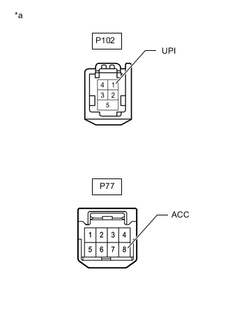
*a Front view of wire harness connector
(to No. 1 Stereo Jack Adapter Assembly)
Measure the voltage according to the value(s) in the table below.
Standard Voltage Tester Connection Switch Condition Specified Condition P102-1 (UPI) - Body ground Power switch on (ACC) 5 V P77-8 (ACC) - Body ground Power switch on (ACC) 11 to 14 V Result Proceed to OK NG
OK 
REPLACE NO. 1 STEREO JACK ADAPTER ASSEMBLY Click here
NG 
-
-
CHECK HARNESS AND CONNECTOR (RADIO RECEIVER ASSEMBLY - NO. 1 STEREO JACK ADAPTER ASSEMBLY)
-
Disconnect the P43 radio receiver assembly connector.
-
Disconnect the P77 No. 1 stereo jack adapter assembly connector.
-
Measure the resistance according to the value(s) in the table below.
Standard Resistance Tester Connection Condition Specified Condition P43-16 (ACC) - P77-8 (ACC) Always Below 1 Ω P43-16 (ACC) or P77-8 (ACC) - Body ground Always 10 kΩ or higher Result Proceed to OK NG
NG
REPAIR OR REPLACE HARNESS OR CONNECTOR
OK
-
-
CHECK HARNESS AND CONNECTOR (RADIO RECEIVER ASSEMBLY - NO. 1 STEREO JACK ADAPTER ASSEMBLY)
-
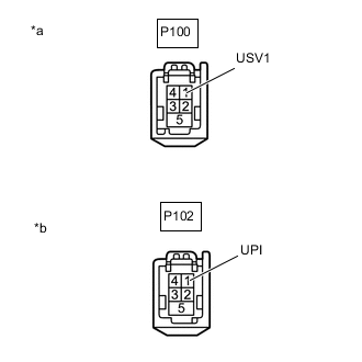
*a Front view of wire harness connector
(to Radio Receiver Assembly)
*b Front view of wire harness connector
(to No. 1 Stereo Jack Adapter Assembly)
Disconnect the P100 radio receiver assembly connector.
-
Disconnect the P102 No. 1 stereo jack adapter assembly connector.
-
Measure the resistance according to the value(s) in the table below.
Standard Resistance Tester Connection Condition Specified Condition P100-1 (USV1) - P102-1 (UPI) Always Below 1 Ω P100-1 (USV1) or P102-1 (UPI) - Body ground Always 10 kΩ or higher Result Proceed to OK NG
OK
REPLACE RADIO RECEIVER ASSEMBLY Click here
NG
REPAIR OR REPLACE HARNESS OR CONNECTOR
-