AUDIO AND VISUAL SYSTEM, Diagnostic DTC:C1622
| DTC Code | DTC Name |
|---|---|
| C1622 | Back Camera Disconnected |
DESCRIPTION
This DTC is stored if the radio receiver assembly judges that the signals or signal lines between the television camera assembly and the multi-display are not normal as a result of its self check.
| DTC No. | Detection Item | DTC Detection Condition | Trouble Area |
|---|---|---|---|
| C1622 | Back Camera Disconnected | Open or short in the television camera assembly signal circuit |
|
WIRING DIAGRAM
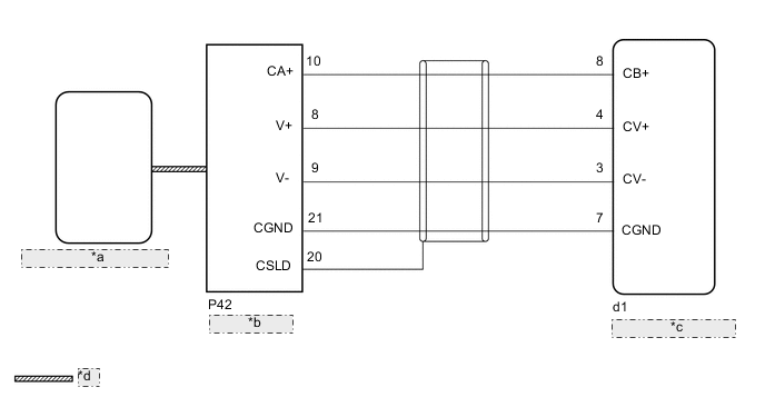
| *a | Radio Receiver Assembly |
| *b | Multi-display |
| *c | Television Camera Assembly |
| *d | AVC-LAN Communication Line |
CAUTION / NOTICE / HINT
Note
-
If the cable was disconnected from and reconnected to the negative (-) auxiliary battery terminal, the estimated course lines may not be displayed on the image of the area behind the vehicle. In this case, perform "Correct the Steering Angle Neutral Point".
-
Depending on the parts that are replaced or operations that are performed during vehicle inspection or maintenance, calibration of other systems as well as the parking assist monitor system may be needed.
-
The following malfunctions may occur if a radio receiver assembly from another vehicle is installed to this vehicle. Therefore, when replacing the radio receiver assembly, be sure to replace it with new one.
-
Communication malfunction DTC is output
-
Does not operate normally
Tech Tips
Depending on the parts that are replaced during vehicle inspection or maintenance, performing initialization, registration or calibration may be needed. Refer to Precaution for Audio and Visual System.
PROCEDURE
-
CHECK HARNESS AND CONNECTOR (TELEVISION CAMERA ASSEMBLY - MULTI-DISPLAY)
-
Disconnect the d1 television camera assembly connector.
-
Disconnect the P42 multi-display connector.
-
Measure the resistance according to the value(s) in the table below.
Standard Resistance Tester Connection Condition Specified Condition d1-8 (CB+) - P42-10 (CA+) Always Below 1 Ω d1-4 (CV+) - P42-8 (V+) Always Below 1 Ω d1-3 (CV-) - P42-9 (V-) Always Below 1 Ω d1-7 (CGND) - P42-21 (CGND) Always Below 1 Ω d1-8 (CB+) or P42-10 (CA+) - Body ground Always 10 kΩ or higher d1-4 (CV+) or P42-8 (V+) - Body ground Always 10 kΩ or higher d1-3 (CV-) or P42-9 (V-) - Body ground Always 10 kΩ or higher d1-7 (CGND) or P42-21 (CGND) - Body ground Always 10 kΩ or higher Result Proceed to OK NG
NG 
REPAIR OR REPLACE HARNESS OR CONNECTOR
OK 
-
-
CHECK MULTI-DISPLAY (CA+, CGND)
-
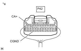
*a Component with harness connected
(Multi-display)
Remove the multi-display with the connector still connected.
-
Measure the voltage according to the value(s) in the table below.
Standard Voltage Tester Connection Switch Condition Specified Condition P42-10 (CA+) - P42-21 (CGND) Power switch on (ACC) 5.5 to 7.05 V -
Measure the resistance according to the value(s) in the table below.
Standard Resistance Tester Connection Condition Specified Condition P42-21 (CGND) - Body ground Always Below 1 Ω Result Proceed to OK NG
NG
REPLACE MULTI-DISPLAY Click here
OK
-
-
CHECK TELEVISION CAMERA ASSEMBLY
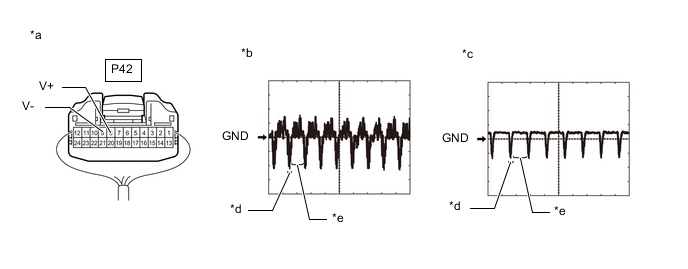
*a Component with harness connected
(multi-display)
*b Waveform 1 *c Waveform 2 *d Synchronization Signal *e Video Waveform - -
-
Remove the multi-display with the connector still connected.
-
Check the waveform of the television camera assembly using an oscilloscope.
Item Content Measurement terminal P42-8 (V+) - P42-9 (V-) Measurement setting 200 mV/DIV., 50 μsec./DIV. Condition Waveform 1: Power switch on (READY), shift position in R, camera lens is not covered, displaying an image.
Waveform 2: Power switch on (READY), shift position in R, camera lens is covered, blacking out the screen.
Tech Tips
-
The video waveform changes according to the image sent by the television camera assembly.
-
The video waveform is constantly output when the power switch is on (ACC).
OK Waveform is as shown in the illustration. Result Proceed to OK NG -
NG
REPLACE TELEVISION CAMERA ASSEMBLY Click here
OK
-
-
CHECK MULTI-DISPLAY
-
Replace the multi-display with a new or known good one.
-
Clear the DTCs.
Body Electrical > Navigation System > Clear DTCs -
Check for DTCs and check that no DTCs are output.
Body Electrical > Navigation System > Trouble CodesResult Result Proceed to DTC C1622 is not output A DTC C1622 is output B
A
END (MULTI-DISPLAY IS DEFECTIVE)
B
REPLACE RADIO RECEIVER ASSEMBLY Click here
-