STEERING LINKAGE REASSEMBLY

PROCEDURE
-
INSTALL NO. 2 STEERING RACK BOOT
-
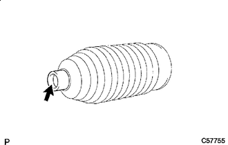

Lithium Soap Base Glycol Grease Apply lithium soap base glycol grease to the inside of the small opening of the No. 2 steering rack boot.
-
Install the No. 2 steering rack boot to the groove of the rack housing.
Note
-
Be careful not to damage or twist the No. 2 steering rack boot.
-
Make sure that the No. 2 steering rack boot is free of rust and foreign matter.
-
Make sure that the boot is free of water, rust, foreign matter, etc.
-
Do not touch the inside of the rack boot or rack bar when performing installation.
-
-
-
INSTALL NO. 1 STEERING RACK BOOT
Tech Tips
Perform the same procedure as for the No. 2 steering rack boot.
-
INSTALL NO. 2 STEERING RACK BOOT CLAMP (for LH Side)
-
Temporarily install a new No. 2 steering rack boot clamp to the No. 2 steering rack boot.
Note
Do not damage the No. 2 steering rack boot.
Tech Tips
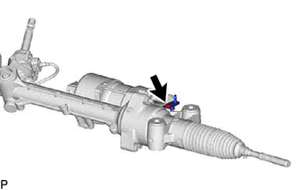
Make sure that the protrusion of the No. 2 steering rack boot clamp is positioned within the area shown in the illustration.
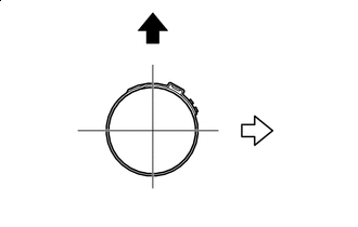
Top of Vehicle 
Rear of Vehicle -
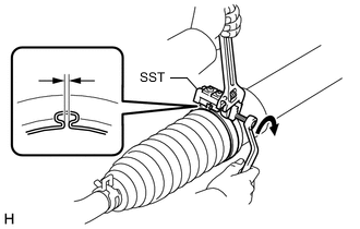
Using SST, install the No. 2 steering rack boot clamp as shown in the illustration.
- SST
- 09521-24010
Note
-
Do not pinch the No. 2 steering rack boot clamp excessively.
-
Be careful not to damage or twist the No. 2 steering rack boot.
-
Remove SST and measure the clearance of the No. 2 steering rack boot clamp.
Clearance 2.5 to 4.0 mm (0.0984 to 0.157 in.)
-
-
INSTALL NO. 2 STEERING RACK BOOT CLAMP (for RH Side)
Tech Tips
Perform the same procedure as for the LH side.
-
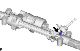
INSTALL STEERING RACK BOOT CLIP (for LH Side)
-
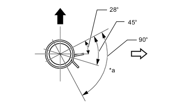
*a Clip Tab Positioning Area Top of Vehicle Rear of Vehicle Using pliers, install the steering rack boot clip.
Tech Tips
Make sure that the tabs of the clip are facing the rear of the vehicle.
-
-
INSTALL STEERING RACK BOOT CLIP (for RH Side)
Tech Tips
Perform the same procedure as for the LH side.
-
INSPECT RACK AND PINION POWER STEERING GEAR ASSEMBLY
-
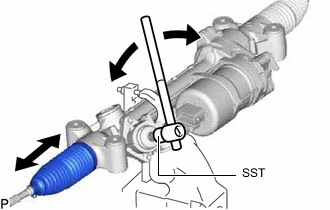
Using SST, turn the pinion shaft and check that the left and the right steering rack boots expand and contract smoothly.
- SST
- 09616-00011
If the operation cannot be performed as specified, use new steering rack boot clamps and reinstall the steering rack boots.
-
-
INSTALL TIE ROD ASSEMBLY LH
-
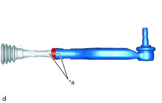
*a Matchmark Install the lock nut and tie rod assembly LH to the steering rack end sub-assembly until the matchmarks are aligned.
Tech Tips
After adjusting toe-in, tighten the lock nut.
-
-
INSTALL TIE ROD ASSEMBLY RH
Tech Tips
Perform the same procedure as for the LH side.
-
INSTALL WIRE HARNESS CLAMP BRACKET (for LHD)
-
Install the wire harness clamp bracket with the bolt.
- Torque:
- 12.5 N*m { 127 kgf*cm, 9 ft.*lbf }
-
-
INSTALL WIRE HARNESS CLAMP BRACKET (for RHD)
-
Install the wire harness clamp bracket with the bolt.
- Torque:
- 12.5 N*m { 127 kgf*cm, 9 ft.*lbf }
-