STEERING LINKAGE REMOVAL

CAUTION / NOTICE / HINT
The necessary procedures (adjustment, calibration, initialization, or registration) that must be performed after parts are removed, installed, or replaced during the rack and pinion power steering gear assembly removal/installation are shown below.
| Replacement Part or Procedure | Necessary Procedure | Effect/Inoperative when not Performed | Link |
|---|---|---|---|
| Disconnect cable from negative auxiliary battery terminal | Memorize steering angle neutral point | LKA/LDA system | |
| Pre-collision system | |||
| Parking assist monitor system | |||
| Steering sensor zero point calibration | Variable gear ratio steering system | ||
| Rack and pinion power steering gear assembly |
|
|
|
| Parts between the steering wheel and tires have been removed/installed, replaced or adjusted | Perform Actuator Angle Neutral Point Calibration and Initialization |
|
Tech Tips
-
Use the same procedure for RHD and LHD vehicles.
-
The procedure listed below is for LHD vehicles.
PROCEDURE
-
PRECAUTION
Note
After turning the power switch off, waiting time may be required before disconnecting the cable from the negative (-) auxiliary battery terminal. Therefore, make sure to read the disconnecting the cable from the negative (-) auxiliary battery terminal notices before proceeding with work.
-
REMOVE NO. 2 DECK BOARD
-
DISCONNECT CABLE FROM NEGATIVE AUXILIARY BATTERY TERMINAL
Note
When disconnecting the cable, some systems need to be initialized after the cable is reconnected.
-
ALIGN FRONT WHEELS FACING STRAIGHT AHEAD
-
SECURE STEERING WHEEL
-
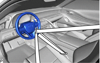
Secure the steering wheel with the seat belt in order to prevent rotation.
Tech Tips
This operation is useful to prevent damage to the spiral cable.
-
-
REMOVE FRONT WHEELS
-
REMOVE NO. 1 ENGINE UNDER COVER ASSEMBLY
-
REMOVE NO. 2 ENGINE UNDER COVER ASSEMBLY
-
REMOVE STRUT BAR BRACKET SUPPORT SUB-ASSEMBLY
-
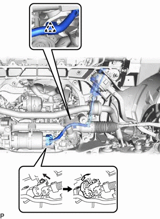
SEPARATE STEERING SLIDING WITH SHAFT YOKE SUB-ASSEMBLY
-
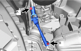
Loosen the bolt (A).
Note
Do not remove the bolt (A).
-
Remove the bolt (B).
-
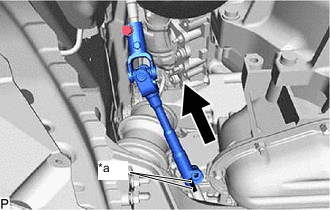
*a Matchmark Slide the steering sliding with shaft yoke sub-assembly and put matchmarks on the steering sliding with shaft yoke sub-assembly and the rack and pinion power steering gear assembly.
-
Separate the steering sliding with shaft yoke sub-assembly from the rack and pinion power steering gear assembly.
-
-
SEPARATE TIE ROD ASSEMBLY LH
-
Remove the clip and nut.
-
Install 2 spacers (SST spacer B) to the steering knuckle LH as shown in the illustration.
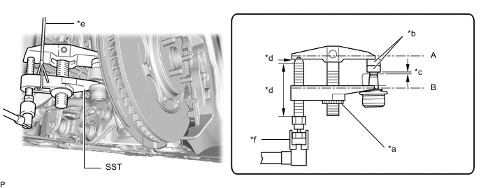
*a Center Nut *b SST (Spacer B) *c 1 mm (0.0394 in.) *d Molybdenum grease application area *e String *f Place wrench here - SST
- 09960-20010 ( 09961-02060 )
Note
Make sure that the clearance between the tie rod assembly LH and spacers (SST spacer B) is 1 mm (0.0394 in.) or more to prevent damage to SST.
-
Using SST, separate the tie rod assembly LH from steering knuckle LH.
- SST
- 09960-20010 ( 09961-02010 )
CAUTION:
Apply molybdenum grease to the bolt threads and the tip of SST.
Note
-
Be sure to tighten the string firmly to secure SST to the steering knuckle to prevent SST from falling off.
-
Install SST so that (A) and (B) shown in the illustration are parallel. Otherwise, the ball joint dust cover may be damaged.
-
Be sure to place the wrench on the part shown in the illustration.
-
Do not damage the ball joint dust cover.
-
Do not damage the steering knuckle.
-
Do not damage the front disc brake dust cover.
-
-
SEPARATE TIE ROD ASSEMBLY RH
Tech Tips
Perform the same procedure as for the LH side.
-
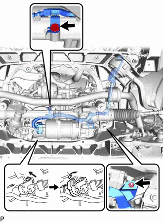
REMOVE RACK AND PINION POWER STEERING GEAR ASSEMBLY
-
for LHD:
-
Disconnect the wire harness clamp and connector, and then disconnect the wire harness from the rack and pinion power steering gear assembly.
Tech Tips
Pull up the lock and release the lock lever to disconnect the connector which uses a lock.
-
-
for RHD:
-
Remove the bolt and nut, and disconnect the wire harness clamp and connector, and then disconnect the wire harness from the rack and pinion power steering gear assembly.
Tech Tips
Pull up the lock and release the lock lever to disconnect the connector which uses a lock.
-
-
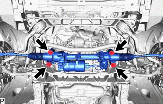
Remove the 4 bolts, 4 nuts and rack and pinion power steering gear assembly from the front suspension crossmember sub-assembly.
-