TILT AND TELESCOPIC MANUAL SWITCH INSTALLATION
CAUTION / NOTICE / HINT
Note
-
Do not replace the spiral cable with sensor sub-assembly with the battery connected and the power switch on (IG).
-
Do not rotate the spiral cable with sensor sub-assembly without the steering wheel assembly installed, with the battery connected and the power switch on (IG).
-
Ensure that the steering wheel assembly is installed and aligned straight when inspecting the steering sensor.
Tech Tips
-
Use the same procedure for RHD and LHD vehicles.
-
The procedure listed below is for LHD vehicles.
PROCEDURE
-
INSTALL TILT AND TELESCOPIC SWITCH
-
Engage the claw to install the tilt and telescopic switch.
-
Connect the tilt and telescopic connector to the tilt and telescopic switch.
-
Connect the airbag connector to the spiral cable with sensor sub-assembly.
-
-
INSTALL LOWER STEERING COLUMN COVER SUB-ASSEMBLY
-
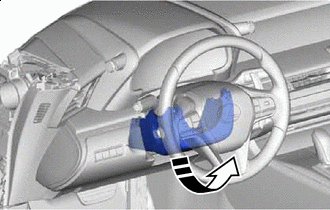

Install in this Direction Insert the lower steering column cover sub-assembly in the direction indicated by the arrow.
Note
Do not damage the tilt and telescopic switch.
-
Engage the 4 claws to install the lower steering column cover sub-assembly to the upper steering column cover.
-
Install the 3 screws.
-
-
CONNECT CABLE TO NEGATIVE AUXILIARY BATTERY TERMINAL
Note
When disconnecting the cable, some systems need to be initialized after the cable is reconnected.
-
INSTALL NO. 2 DECK BOARD
-
CUSTOMIZE POWER TILT AND POWER TELESCOPIC STEERING COLUMN SYSTEM
-
Reset the auto tilt away function setting to the previous condition by changing the customize parameter.
-
-
PERFORM VARIABLE GEAR RATIO STEERING SYSTEM CALIBRATION (w/ VGRS)