HEATED STEERING WHEEL SYSTEM, Diagnostic DTC:B14B7
| DTC Code | DTC Name |
|---|---|
| B14B7 | Lost Communication with Steering Heater ECU |
DESCRIPTION
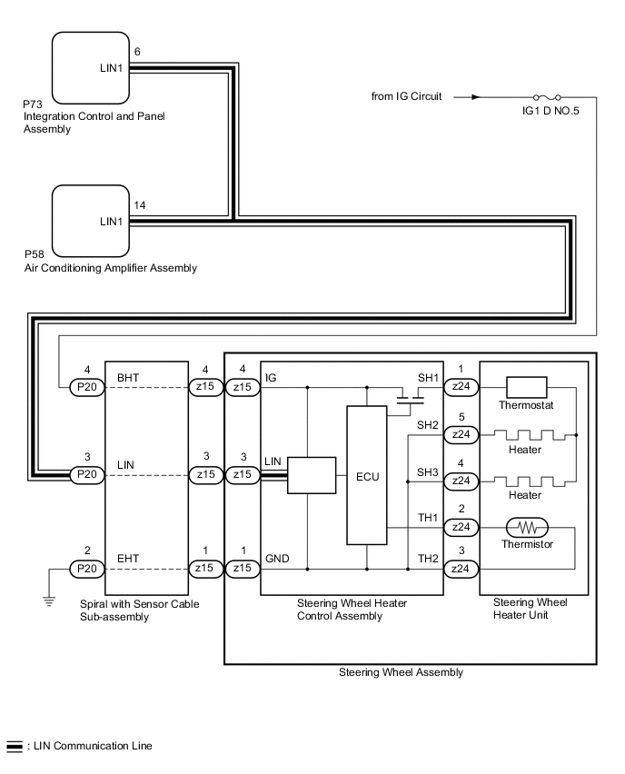
The steering wheel heater control assembly communicates with the air conditioning amplifier assembly via LIN communication.
B14B7 is output when a communication malfunction is detected with the air conditioner amplifier assembly and steering wheel heater control assembly (steering wheel assembly).
| DTC No. | Detection Item | DTC Detection Condition | Trouble Area |
|---|---|---|---|
| B14B7 | Lost Communication with Steering Heater ECU |
|
|
WIRING DIAGRAM
CAUTION / NOTICE / HINT
Note
-
Inspect the fuses for circuits related to this system before performing the following procedure.
-
The vehicle is equipped with a Supplemental Restraint System (SRS) which includes components such as airbags. Before servicing (including removal or installation of parts), be sure to read the precaution for Supplemental Restraint System.
PROCEDURE
-
CHECK FOR DTCs
-
Check for DTCs.
Body Electrical > Air Conditioner > Trouble CodesResult Result Proceed to Only DTC B14B7 is output A DTC B14B2 and B14B7 are output B
B 
CHECK HARNESS OR CONNECTOR (SPIRAL WITH SENSOR CABLE SUB-ASSEMBLY - AIR CONDITIONING AMPLIFIER ASSEMBLY AND INTEGRATION CONTROL & PANEL ASSEMBLY) Click here
A 
-
-
CHECK HARNESS OR CONNECTOR (STEERING WHEEL HEATER CONTROL ASSEMBLY POWER SOURCE CIRCUIT)
-
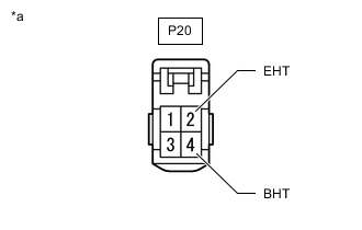
*a Front view of wire harness connector
(to Spiral with Sensor Cable Sub-assembly)
Disconnect the P20 spiral with sensor cable sub-assembly connector.
-
Measure the voltage according to the value(s) in the table below.
Standard Voltage Tester Connection Condition Specified Condition P20-4 (BHT) - Body ground Power switch on (IG) 11 to 14 V P20-4 (BHT) - Body ground Power switch off Below 1 V -
Measure the resistance according to the value(s) in the table below.
Standard Resistance Tester Connection Condition Specified Condition P20-2 (EHT) - Body ground Always Below 1 Ω Result Proceed to OK NG
NG 
REPAIR OR REPLACE HARNESS OR CONNECTOR (STEERING WHEEL HEATER CONTROL ASSEMBLY POWER SOURCE CIRCUIT)
OK
-
-
INSPECT SPIRAL WITH SENSOR CABLE SUB-ASSEMBLY
-
Remove the spiral with sensor cable sub-assembly.
-
Inspect the spiral with sensor cable sub-assembly.
Result Proceed to OK NG
NG
REPLACE SPIRAL WITH SENSOR CABLE SUB-ASSEMBLY Click here
OK
-
-
CHECK HARNESS OR CONNECTOR (SPIRAL WITH SENSOR CABLE SUB-ASSEMBLY - AIR CONDITIONING AMPLIFIER ASSEMBLY AND INTEGRATION CONTROL AND PANEL ASSEMBLY)
-
Disconnect the P20 spiral with sensor cable sub-assembly connector.
-
Disconnect the P58 air conditioning amplifier assembly connector.
-
Disconnect the P73 integration control and panel assembly connector.
-
Measure the resistance according to the value(s) in the table below.
Standard Resistance Tester Connection Condition Specified Condition P20-3 (LIN) - P58-14 (LIN1) Always Below 1 Ω Result Proceed to OK NG
OK
REPLACE STEERING WHEEL HEATER CONTROL ASSEMBLY Click here
NG
REPAIR OR REPLACE HARNESS OR CONNECTOR (SPIRAL WITH SENSOR CABLE SUB-ASSEMBLY - AIR CONDITIONING AMPLIFIER ASSEMBLY AND INTEGRATION CONTROL AND PANEL ASSEMBLY)
-
-
CHECK HARNESS OR CONNECTOR (SPIRAL WITH SENSOR CABLE SUB-ASSEMBLY - AIR CONDITIONING AMPLIFIER ASSEMBLY AND INTEGRATION CONTROL & PANEL ASSEMBLY)
-
Disconnect the P20 spiral with sensor cable sub-assembly connector.
-
Disconnect the P58 air conditioning amplifier assembly connector.
-
Disconnect the P73 integration control and panel assembly connector.
-
Measure the resistance according to the value(s) in the table below.
Standard Resistance Tester Connection Condition Specified Condition P20-3 (LIN) - P58-14 (LIN1) Always Below 1 Ω P20-3 (LIN), P58-14 (LIN1) or P73-6 (LIN1) - Body ground Always 10 kΩ or higher Result Proceed to OK NG
NG
REPAIR OR REPLACE HARNESS OR CONNECTOR (SPIRAL WITH SENSOR CABLE SUB-ASSEMBLY - AIR CONDITIONING AMPLIFIER ASSEMBLY AND INTEGRATION CONTROL AND PANEL ASSEMBLY)
OK
-
-
CHECK FOR DTCs
-
Clear the DTCs.
Body Electrical > Air Conditioner > Clear DTCs -
Disconnect the P73 integration control and panel assembly connector.
-
Make sure that the DTC detection conditions are met.
Tech Tips
If the detection conditions are not met, the system cannot detect the malfunction.
-
Check for DTCs.
Body Electrical > Air Conditioner > Trouble CodesResult Result Proceed to Only DTC B14B2 is output A DTC B14B2 and B14B7 are output B
A
REPLACE INTEGRATION CONTROL AND PANEL ASSEMBLY Click here
B
-
-
CHECK FOR DTCs
-
Clear the DTCs.
Body Electrical > Air Conditioner > Clear DTCs -
Disconnect the z15 spiral with sensor cable sub-assembly connector.
-
Make sure that the DTC detection conditions are met.
Tech Tips
If the detection conditions are not met, the system cannot detect the malfunction.
-
Check for DTCs.
Body Electrical > Air Conditioner > Trouble CodesResult Result Proceed to Only DTC B14B7 is output A DTC B14B2 and B14B7 are output B
A
REPLACE STEERING WHEEL HEATER CONTROL ASSEMBLY Click here
B
-
-
CHECK FOR DTCs
-
Clear the DTCs.
Body Electrical > Air Conditioner > Clear DTCs -
Disconnect the P20 spiral with sensor cable sub-assembly connector.
-
Make sure that the DTC detection conditions are met.
Tech Tips
If the detection conditions are not met, the system cannot detect the malfunction.
-
Check for DTCs.
Body Electrical > Air Conditioner > Trouble CodesResult Result Proceed to Only DTC B14B7 is output A DTC B14B2 and B14B7 are output B
A
REPLACE SPIRAL WITH SENSOR CABLE SUB-ASSEMBLY Click here
B
REPLACE AIR CONDITIONING AMPLIFIER ASSEMBLY Click here
-