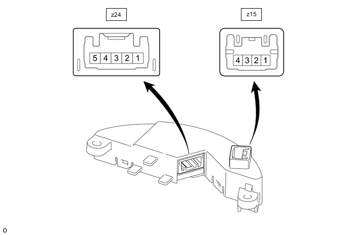
HEATED STEERING WHEEL SYSTEM TERMINALS OF ECU
-
STEERING WHEEL HEATER CONTROL ASSEMBLY
Tech Tips
Perform the inspection from the harness side with the connectors connected.
-
Measure the voltage or resistance according to the value(s) in the table below.
Terminal No. (Symbol) Terminal Description Condition Specified Condition z15-1 (GND) - Body ground Ground Always Below 1 Ω z15-3 (LIN) - Body ground LIN communication signal Power switch on (IG) Pulse generation z15-4 (IG) - Body ground IG power supply Power switch on (IG) 11 to 14 V z24-1 (SH1) - Body ground Heater output signal Power switch on (IG), Heated steering wheel system operating Below 1 V z24-2 (TH1) - Body ground Thermistor input signal Power switch on (IG), Heated steering wheel system operating 11 to 14 V*1 z24-3 (TH2) - Body ground Thermistor ground Power switch on (IG), Heated steering wheel system operating 2.5 to 4.8 V*2 z24-4 (SH3) - Body ground Heater ground Power switch on (IG), Heated steering wheel system operating Below 1 V z24-5 (SH2) - Body ground Heater ground Power switch on (IG), Heated steering wheel system operating Below 1 V Tech Tips
-
*1: The current to the heater turns ON/OFF depending on the temperature of the thermistor. As a result, it may take several minutes before a voltage value is output.
-
*2: When ambient temperature is 0 to 40°C (32 to 104°F).
-
-