DYNAMIC REAR STEERING ECU REMOVAL
CAUTION / NOTICE / HINT
The necessary procedures (adjustment, calibration, initialization, or registration) that must be performed after parts are removed, installed, or replaced during the rear steering control ECU removal/installation are shown below.
| Replacement Part or Procedure | Necessary Procedure | Effect/Inoperative when not Performed | Link |
|---|---|---|---|
| Disconnect cable from negative auxiliary battery terminal | Memorize steering angle neutral point | LKA/LDA system | |
| Pre-collision system | |||
| Parking assist monitor system | |||
| Steering sensor zero point calibration | Variable gear ratio steering system | ||
| DRS ECU (rear steering control ECU) | Perform Neutral Position Memorization and Motor Rotation Angle Sensor Calibration |
|
PROCEDURE
-
PRECAUTION
Note
After turning the power switch off, waiting time may be required before disconnecting the cable from the negative (-) auxiliary battery terminal. Therefore, make sure to read the disconnecting the cable from the negative (-) auxiliary battery terminal notices before proceeding with work.
-
REMOVE NO. 2 DECK BOARD
-
DISCONNECT CABLE FROM NEGATIVE AUXILIARY BATTERY TERMINAL
Note
When disconnecting the cable, some systems need to be initialized after the cable is reconnected.
-
REMOVE NO. 1 DECK BOARD
-
REMOVE LUGGAGE COMPARTMENT TRIM COVER RH
-
REMOVE SIDE TRIM BOX
-
REMOVE REAR FLOOR FINISH PLATE
-
REMOVE NO. 1 LUGGAGE COMPARTMENT LIGHT ASSEMBLY
-
REMOVE FRONT LUGGAGE COMPARTMENT TRIM COVER
-
REMOVE INNER LUGGAGE COMPARTMENT TRIM COVER RH
-
REMOVE NO. 2 DECK BOARD BRACKET
-
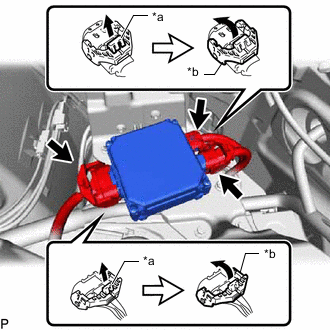
*a Lock of the Lock Lever *b Lock Lever Disconnect the 3 connectors from the rear steering control ECU.
Tech Tips
When disconnecting the connector with lock lever, pull out the lock of the lock lever and turn the lock lever as shown in the illustration.
-
Disconnect the 3 connectors.
-
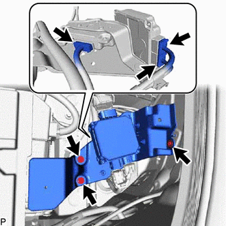
Remove the 3 bolts and No. 2 deck board bracket.
-
-
REMOVE STEREO COMPONENT EQUALIZER ASSEMBLY
-
REMOVE REAR STEERING CONTROL ECU
-
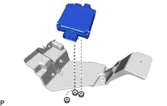
Remove the 3 nuts and rear steering control ECU.
-