ELECTRIC PARKING BRAKE ACTUATOR REMOVAL
CAUTION / NOTICE / HINT
The necessary procedures (adjustment, calibration, initialization, or registration) that must be performed after parts are removed, installed, or replaced during the parking brake actuator with bracket assembly removal/installation are shown below.
| Replacement Part or Procedure | Necessary Procedure | Effect/Inoperative when not Performed | Link |
|---|---|---|---|
| Parking brake with bracket actuator assembly (Including removal and installation) |
|
Electric parking brake system | |
|
Parking brake bedding | Electric parking brake system | |
| Suspension, tires, etc*1 | Television camera assembly optical axis (Back camera position setting) | Parking assist monitor system | |
| Rear steering link assembly or rear suspension have been removed/installed, replaced, or adjusted |
|
Steering wheel off-center | |
| Disconnect cable from negative auxiliary battery terminal | Memorize steering angle neutral point | LKA/LDA system | |
| Pre-collision system | |||
| Parking assist monitor system | |||
| Steering sensor zero point calibration | Variable gear ratio steering system |
*1: The vehicle height changes due to suspension or tire replacement.
PROCEDURE
-
RELEASE PARKING BRAKE
-
Turn off the electric parking brake AUTO function.
-
With the power switch on (IG), operate the electric parking brake switch assembly to release the parking brake. Then turn the power switch off.
Tech Tips
If the parking brake cannot be released, perform the forced release of parking brake.
-
-
FORCED RELEASE PARKING BRAKE
Note
-
If the parking brake cannot be released by operating the electric parking brake switch assembly, perform forced release by using electric release SST.
-
If the parking brake cannot be released even when using electric release SST due to a malfunction in the parking brake actuator with bracket assembly, perform the following procedures.
-
Remove the No. 1 differential support protector.
-
Using a 4 mm long socket hexagon wrench, remove the bolt and release cable cover.
-

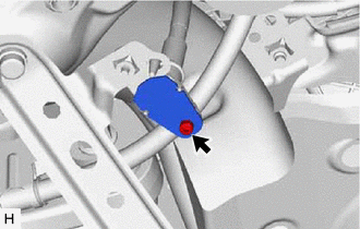
Pull Out Direction Remove the cap.
-
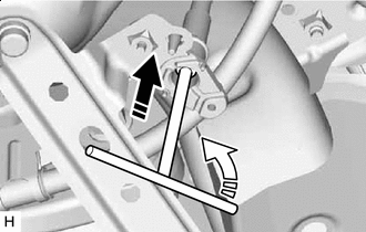
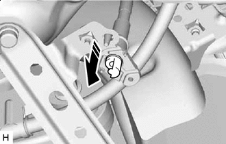
Push Direction 
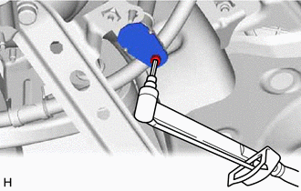
Rotate Direction Insert a 4 mm socket hexagon wrench into the release cable and while pushing down, rotate it counterclockwise.
-
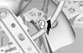
Install in this Direction After checking that the parking brake has been released, install the cap.
Note
When installing the cap, make sure it inserted facing the correct direction.
-
Using a 4 mm long socket hexagon wrench, install the release cable cover with the bolt.
- Torque:
- 3.0 N*m { 31 kgf*cm, 27 in.*lbf }
-
Install the No. 1 differential support protector.
-
-
PRECAUTION
Note
After turning the power switch off, waiting time may be required before disconnecting the cable from the negative (-) auxiliary battery terminal. Therefore, make sure to read the disconnecting the cable from the negative (-) auxiliary battery terminal notices before proceeding with work.
-
REMOVE REAR SUSPENSION MEMBER SUB-ASSEMBLY
-
REMOVE PARKING BRAKE ACTUATOR ASSEMBLY WITH BRACKET
-
Remove the bolt and 6 nuts to disconnect the parking brake actuator assembly with bracket from the rear suspension member sub-assembly.
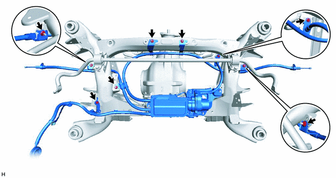
-
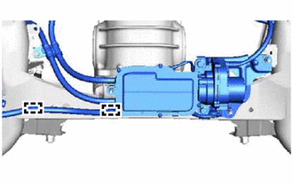
Disconnect the 2 clamps from the rear suspension member sub-assembly.
-
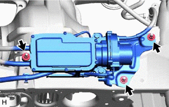
Remove the 3 nuts and parking brake actuator assembly with bracket.
-
-
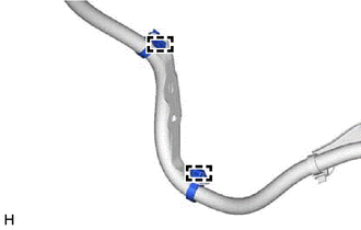
REMOVE CABLE SUPPORT BRACKET
-
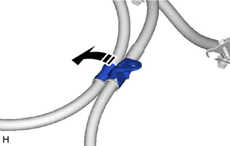
Remove the cable support bracket in the direction indicated by the arrow shown in the illustration.
-
-
REMOVE NO. 2 CABLE SUPPORT BRACKET
-
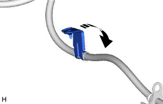
Remove the No. 2 cable support bracket in the direction indicated by the arrow shown in the illustration.
-
-
REMOVE NO. 1 CABLE SUPPORT BRACKET
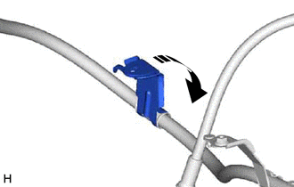
-
Remove the No. 1 cable support bracket in the direction indicated by the arrow shown in the illustration.
-
-
REMOVE NO. 2 ACTUATOR HARNESS CLAMP
-
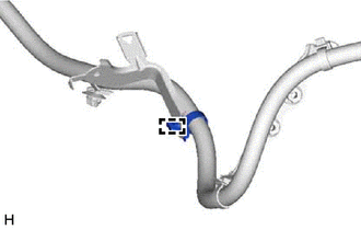
Disconnect the clamp and remove the No. 2 actuator harness clamp.
-
-
REMOVE NO. 1 ACTUATOR HARNESS CLAMP
-
Disconnect the 2 clamps and remove the No. 1 actuator harness clamp.
-