ACTIVE REAR WING SWITCH INSPECTION
PROCEDURE
-
INSPECT NO. 4 COMBINATION SWITCH ASSEMBLY
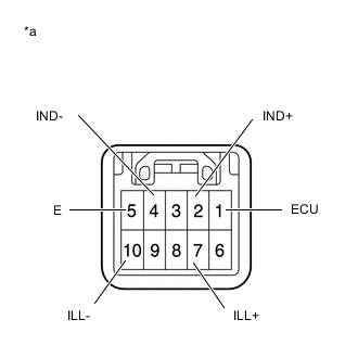
*a Component without harness connected
(No. 4 combination switch assembly)
-
Check the switch.
-
Measure the resistance according to the value(s) in the table below.
Standard Resistance Tester Connection Condition Specified Condition 1(ECU) - 5(E) Spoiler control switch pressed Below 1 Ω Spoiler control switch not pressed 10 kΩ or higher Tech Tips
If the result is not as specified, replace the No. 4 combination switch assembly.
-
-
Check the switch illumination and indicator light.
-
Apply battery voltage to the spoiler control switch and check that the switch illumination and indicator light illuminates.
OK Battery Connection Specified Condition Battery positive (+) → 2(IND+)
Battery negative (-) → 4(IND-)
Indicator light illuminates Battery positive (+) → 7(ILL+)
Battery negative (-) → 10(ILL-)
Illumination illuminates Tech Tips
If the result is not as specified, replace the No. 4 combination switch assembly.
-
-