FRONT BUMPER DISASSEMBLY
PROCEDURE
-
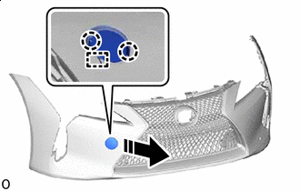
REMOVE FRONT BUMPER MOUNTING BRACKET
-

Remove in this Direction Detach the 2 clips and remove the front bumper mounting bracket.
-
-
REMOVE MILLIMETER WAVE RADAR SENSOR ASSEMBLY (w/ Dynamic Radar Cruise Control System)
-
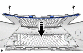
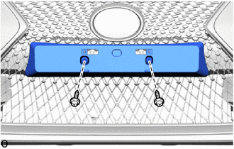
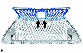
REMOVE RADIATOR GRILLE (OR FRONT PANEL) EMBLEM
-
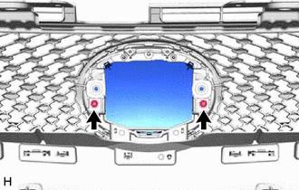
Remove the 2 screws.
-
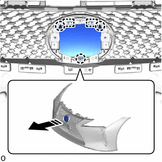
Remove in this Direction Detach the claws and guides and remove the radiator grille (or front panel) emblem.
-
-
REMOVE FRONT BUMPER EXTENTION MOUNTING BRACKET
-
for Type A:
-
Remove the 2 screws and front bumper extension mounting bracket.
-
-
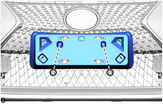
for Type B:
-
Remove the 2 screws and front bumper extension mounting bracket.
-
-
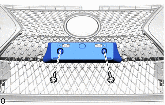
for Type C:
-
Remove the 2 screws and front bumper extension mounting bracket.
-
-
-
REMOVE FRONT TURN SIGNAL LIGHT ASSEMBLY LH
-
REMOVE FRONT TURN SIGNAL LIGHT ASSEMBLY RH
Tech Tips
Use the same procedure described for the LH side.
-
REMOVE NO. 4 ENGINE ROOM WIRE
-
REMOVE FRONT CORNER ULTRASONIC SENSOR
-
REMOVE FRONT CORNER ULTRASONIC SENSOR RETAINER
-
REMOVE FRONT CENTER ULTRASONIC SENSOR
-
REMOVE ULTRASONIC SENSOR CLIP
-
REMOVE LOWER SIDE RADIATOR GRILLE LH
-
Remove in this Direction Detach the claws and remove the lower side radiator grille LH.
-
-
REMOVE LOWER SIDE RADIATOR GRILLE RH
Tech Tips
Use the same procedure described for the LH side.
-
REMOVE FRONT BUMPER GARNISH LH
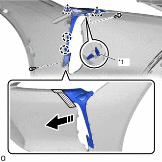
*1 Front Bumper Side Retainer Remove in this Direction 
Protective Tape
-
Apply protective tape around the front bumper garnish LH.
-
Remove the 2 screws and front bumper side retainer.
-
Detach the clips and claws and remove the front bumper garnish LH.
-
Remove the protective tape.
-
-
REMOVE FRONT BUMPER GARNISH
Tech Tips
Use the same procedure described for the LH side.
-
REMOVE HEADLIGHT WASHER COVER
-
REMOVE HEADLIGHT WASHER ACTUATOR SUB-ASSEMBLY LH
-
REMOVE HEADLIGHT WASHER ACTUATOR SUB-ASSEMBLY RH
Tech Tips
Use the same procedure described for the LH side.
-
REMOVE NO. 2 WASHER BRACKET
-
REMOVE WASHER BRACKET
Tech Tips
Use the same procedure described for the LH side.
-
REMOVE NO. 1 FRONT BUMPER SIDE SUPPORT LH
Tech Tips
When removing the No. 1 front bumper side support LH, heat the front bumper cover and No. 1 front bumper side support LH using a heat light.
Standard Item Temperature Front Bumper Cover 20 to 30°C (68 to 86°F) No. 1 Front Bumper Side Support LH CAUTION:
-
Do not touch the heat light and heated parts.
-
Touching the heat light may result in burns.
-
Touching heated parts for a long time may result in burns.
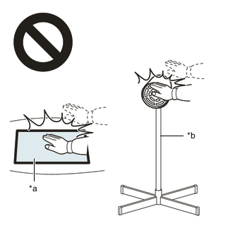
*a Heated Part *b Heat Light
-
Remove the No. 1 front bumper side support LH.
-
-
REMOVE NO. 1 FRONT BUMPER SIDE SUPPORT RH
Tech Tips
Use the same procedure described for the LH side.
-
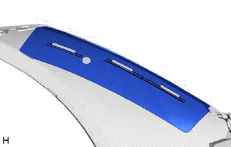
REMOVE NO. 2 MOULDING TAPE
Tech Tips
When removing the No. 2 moulding tape, heat the front bumper cover and No. 2 moulding tape using a heat light.
Standard Item Temperature Front Bumper Cover 20 to 30°C (68 to 86°F) No. 2 Moulding Tape CAUTION:
-
Do not touch the heat light and heated parts.
-
Touching the heat light may result in burns.
-
Touching heated parts for a long time may result in burns.
*a Heated Part *b Heat Light
-
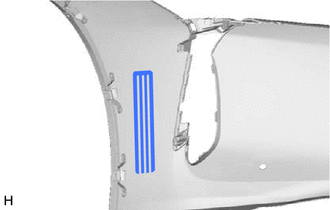
Remove the No. 2 moulding tape.
Tech Tips
Use the same procedure for the RH side and LH side.
-
-
REMOVE FRONT BUMPER HOLE COVER LH
-
Remove in this Direction Detach the claws.
-
Detach the anti-drop hook and remove the front bumper hole cover LH.
-
-
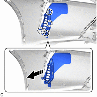
REMOVE FRONT FENDER LINER RETAINER
-
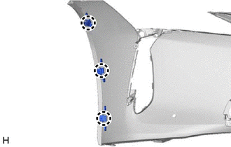
Detach the claw and remove the 3 front fender liner retainers.
Tech Tips
Use the same procedure for the RH side and LH side.
-
-
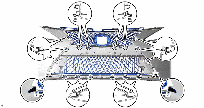
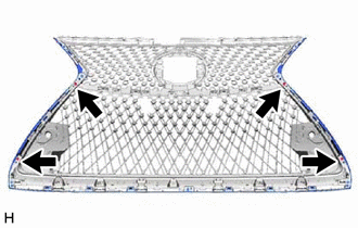
REMOVE RADIATOR GRILLE SUB-ASSEMBLY
-
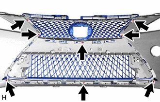
Remove the 8 screws.
-
Detach the claws and guides and remove the radiator grille sub-assembly.
-
-
REMOVE RADIATOR GRILLE MOULDING
-
Remove the 4 screws.
-
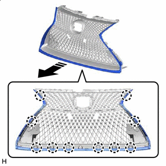
Remove in this Direction Detach the claws and remove the radiator grille moulding.
-
-
REMOVE NO. 2 RADIATOR GRILLE MOULDING
-
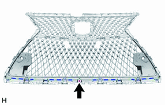
Remove the screw.
-
Remove in this Direction Detach the claws and remove the No. 2 radiator grille moulding.
-
-
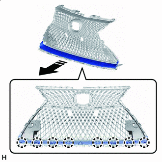
REMOVE UPPER RADIATOR GRILLE
-
Remove the 2 screws.
-
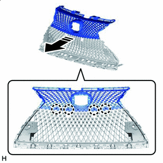
Remove in this Direction Detach the claws and remove the upper radiator grille from the lower radiator grille.
-
-
REMOVE LOWER RADIATOR GRILLE
-
REMOVE HEADLIGHT CLEANER HOSE
-
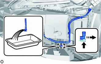
Remove in this Direction Disconnect the headlight cleaner hose and drain the windshield washer fluid.
Tech Tips
Prepare a container before performing the procedure.
-
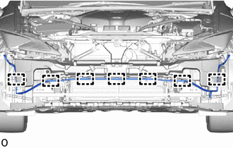
Detach the clamps and remove the headlight cleaner hose.
-
-
REMOVE NO. 2 DECK BOARD
-
PRECAUTION
Note
After turning the engine switch off, waiting time may be required before disconnecting the cable from the negative (-) battery terminal. Therefore, make sure to read the disconnecting the cable from the negative (-) battery terminal notices before proceeding with work.
-
DISCONNECT CABLE FROM NEGATIVE BATTERY TERMINAL
CAUTION:
-
Wait at least 90 seconds after disconnecting the cable from the negative(-) battery terminal to disable the SRS system.
-
If the airbag deploys for any reason, it may cause a serious accident.
Note
When disconnecting the cable, some systems need to be initialized after the cable is reconnected.
-
-
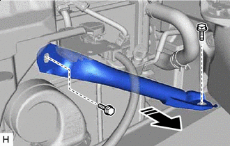
REMOVE NO. 2 FRONT BUMPER MOUNTING BRACKET
-
Check that the engine switch off.
-
Check that the cable is disconnected from the negative (-) battery terminal.
CAUTION:
Wait at least 90 seconds after disconnecting the cable from the negative (-) battery terminal to disable the SRS system.
-
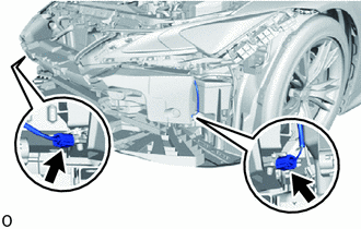
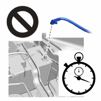
Disconnect the 2 connectors of the pedestrian detection chamber assembly.
Note
When disconnecting any pedestrian detection chamber assembly connector, take care not to damage the pedestrian detection chamber assembly wire harness.
-
Push down the housing lock and slide the CPA. (At this time, the connector cannot be disconnected yet.)
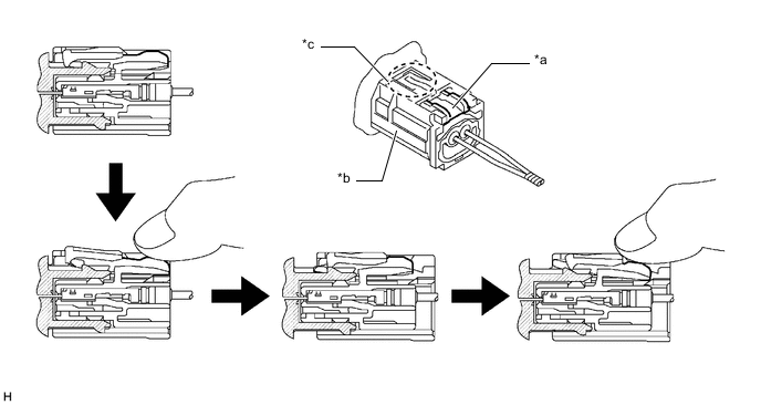
*a Housing Lock *b CPA *c CPA Upper Part - - -
Push the housing lock again and disconnect the connector.
Note
Do not push down the upper part of the CPA shown in the illustration when disconnecting the pedestrian detection chamber assembly connector.
-
After disconnecting the connector, check that the position of the housing lock is correct as shown in the illustration.
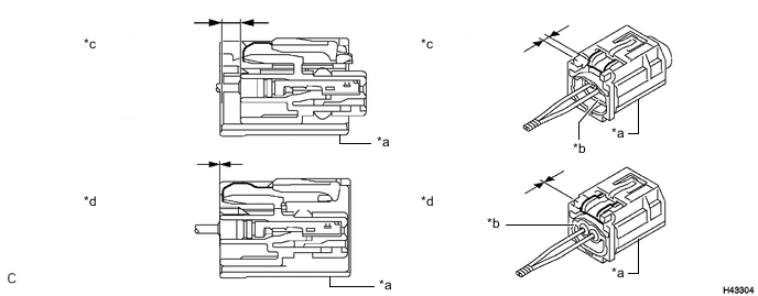
*a CPA *b Housing *c Correct *d Incorrect
-
-
Remove the 2 bolts.
-
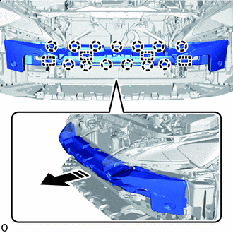
Remove in this Direction Detach the claws and guides and remove the No. 2 front bumper mounting bracket with the front bumper energy absorber.
-
-
REMOVE PEDESTRIAN DETECTION CHAMBER ASSEMBLY
-
REMOVE FRONT BUMPER ENERGY ABSORBER
-
REMOVE HEADLIGHT ASSEMBLY LH
-
REMOVE HEADLIGHT ASSEMBLY RH
Tech Tips
Use the same procedure described for the LH side.
-
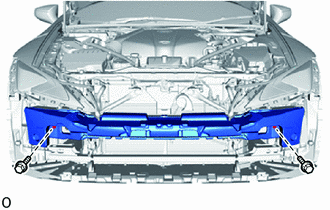
REMOVE LOWER ARM BRACKET BRACE SUB-ASSEMBLY LH
Remove in this Direction
-
Remove the 2 bolts and lower arm bracket brace sub-assembly LH.
-
-
REMOVE LOWER ARM BRACKET BRACE SUB-ASSEMBLY RH
Tech Tips
Use the same procedure described for the LH side.
-
REMOVE FRONT BUMPER REINFORCEMENT SUB-ASSEMBLY
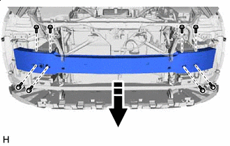
Remove in this Direction
-
Remove the 8 bolts and front bumper reinforcement sub-assembly.
-