ACTIVE REAR WING SYSTEM, Diagnostic DTC:B1319
| DTC Code | DTC Name |
|---|---|
| B1319 | Hall IC Supply Voltage Low |
DESCRIPTION
This DTC is stored when the Hall IC power supply voltage is low.
| DTC No. | Detection Item | DTC Detection Condition | Trouble Area |
|---|---|---|---|
| B1319 | Hall IC Supply Voltage Low | When the voltage at terminal ECUB of the spoiler control ECU assembly is 9 V or more, the difference in voltage at terminals ECUB and CSV is 13 V or more. |
|
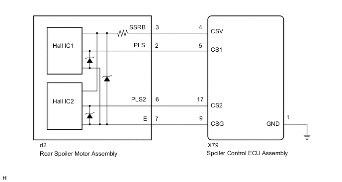
WIRING DIAGRAM
PROCEDURE
-
CHECK CONNECTOR CONNECTION
-
Check that the connectors are properly connected to the spoiler control ECU assembly and rear spoiler drive gear.
OK Connectors are properly connected. Result Proceed to OK NG
NG 
CONNECT CONNECTORS PROPERLY
OK 
-
-
CLEAR DTC
-
Clear the DTCs.
Body Electrical > Active Rear Wing > Clear DTCsResult Proceed to NEXT
NEXT
-
-
CHECK FOR DTC
-
Raise and retract the active rear wing by manual operation.
-
Check for DTCs.
Body Electrical > Active Rear Wing > Trouble CodesOK DTC B1319 is not output. Result Proceed to OK NG
OK
USE SIMULATION METHOD TO CHECK Click here
NG
-
-
CHECK SPOILER CONTROL ECU ASSEMBLY (POWER SUPPLY FOR HALL IC)
-
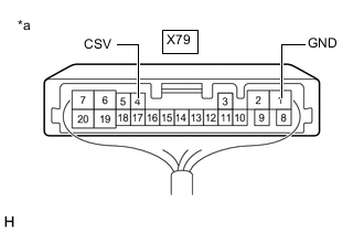
*a Component with harness connected
(Spoiler Control ECU Assembly)
Measure the voltage according to the value(s) in the table below.
Standard Voltage Tester Connection Switch Condition Specified Condition X79-4 (CSV) - X79-1 (GND) Engine switch on (IG) 11 to 14 V Result Proceed to OK NG
NG
REPLACE SPOILER CONTROL ECU ASSEMBLY Click here
OK
-
-
CHECK REAR SPOILER MOTOR ASSEMBLY
-
Disconnect the X79 spoiler control ECU assembly connector.
-
Measure the resistance according to the value(s) in the table below.
Standard Resistance Tester Connection Condition Specified Condition X79-4 (CSV) - X79-1 (GND) Always 10 kΩ or higher X79-4 (CSV) - X79-9 (CSG) Always 10 kΩ or higher Result Proceed to OK NG
OK
REPLACE SPOILER CONTROL ECU ASSEMBLY Click here
NG
-
-
CHECK HARNESS AND CONNECTOR (SPOILER CONTROL ECU ASSEMBLY - REAR SPOILER MOTOR ASSEMBLY)
-
Disconnect the d2 rear spoiler motor assembly connector.
-
Measure the resistance according to the value(s) in the table below.
Standard Resistance Tester Connection Condition Specified Condition X79-4 (CSV) or d2-3 (SSRB) - Body ground Always 10 kΩ or higher X79-9 (CSG) or d2-7 (E) - Body ground Always 10 kΩ or higher Result Proceed to OK NG
OK
REPLACE REAR SPOILER MOTOR ASSEMBLY Click here
NG
REPAIR OR REPLACE HARNESS OR CONNECTOR
-