LIGHTING SYSTEM Exterior Illumination Circuit
DESCRIPTION
Main body ECU (multiplex network body ECU) controls the outside handle lights.
WIRING DIAGRAM
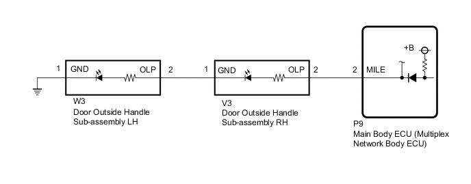
Figure 1. for LHD:

Figure 2. for RHD:
CAUTION / NOTICE / HINT
Note
Before replacing the main body ECU (multiplex network body ECU), refer to Service Bulletin.
PROCEDURE
-
PERFORM ACTIVE TEST USING GTS
-
Perform the Active Test according to the display on the GTS.
Body Electrical > Main Body > Active TestTester Display Measurement Item Control Range Diagnostic Note Exterior Light Outside handle lights OFF or ON -
Body Electrical > Main Body > Active TestTester Display Exterior Light OK Outside handle lights illuminate. Result Result Proceed to OK A NG (for LHD) B NG (for RHD) C
A 
PROCEED TO NEXT SUSPECTED AREA SHOWN IN PROBLEM SYMPTOMS TABLE Click here
C 
INSPECT DOOR OUTSIDE HANDLE SUB-ASSEMBLY RH Click here
B 
-
-
INSPECT DOOR OUTSIDE HANDLE SUB-ASSEMBLY LH
-
Remove the door outside handle sub-assembly LH.
-
Inspect the door outside handle sub-assembly LH.
Result Proceed to OK NG
NG
REPLACE DOOR OUTSIDE HANDLE SUB-ASSEMBLY LH Click here
OK
-
-
INSPECT DOOR OUTSIDE HANDLE SUB-ASSEMBLY RH
-
Remove the door outside handle sub-assembly RH.
-
Inspect the door outside handle sub-assembly RH.
Result Proceed to OK NG
NG
REPLACE DOOR OUTSIDE HANDLE SUB-ASSEMBLY RH Click here
OK
-
-
CHECK HARNESS AND CONNECTOR (MAIN BODY ECU [MULTIPLEX NETWORK BODY ECU] - DOOR OUTSIDE HANDLE SUB-ASSEMBLY LH)
-
Disconnect the P9 main body ECU (multiplex network body ECU) connector.
-
Disconnect the W3 door outside handle sub-assembly LH connector.
-
Measure the resistance according to the value(s) in the table below.
Standard Resistance Tester Connection Condition Specified Condition P9-2 (MILE) - W3-2 (OLP) Always Below 1 Ω P9-2 (MILE) or W3-2 (OLP) - Body ground Always 10 kΩ or higher Result Proceed to OK NG
NG
REPAIR OR REPLACE HARNESS OR CONNECTOR
OK
-
-
CHECK HARNESS AND CONNECTOR (DOOR OUTSIDE HANDLE SUB-ASSEMBLY RH - DOOR OUTSIDE HANDLE SUB-ASSEMBLY LH AND BODY GROUND)
-
Disconnect the V3 door outside handle sub-assembly RH connector.
-
Disconnect the W3 door outside handle sub-assembly LH connector.
-
Measure the resistance according to the value(s) in the table below.
Standard Resistance Tester Connection Condition Specified Condition V3-2 (OLP) - W3-1 (GND) Always Below 1 Ω V3-1 (GND) - Body ground Always Below 1 Ω Result Proceed to OK NG
OK
REPLACE MAIN BODY ECU (MULTIPLEX NETWORK BODY ECU) Click here
NG
REPAIR OR REPLACE HARNESS OR CONNECTOR
-
-
INSPECT DOOR OUTSIDE HANDLE SUB-ASSEMBLY RH
-
Remove the door outside handle sub-assembly RH.
-
Inspect the door outside handle sub-assembly RH.
Result Proceed to OK NG
NG
REPLACE DOOR OUTSIDE HANDLE SUB-ASSEMBLY RH Click here
OK
-
-
INSPECT DOOR OUTSIDE HANDLE SUB-ASSEMBLY LH
-
Remove the door outside handle sub-assembly LH.
-
Inspect the door outside handle sub-assembly LH.
Result Proceed to OK NG
NG
REPLACE DOOR OUTSIDE HANDLE SUB-ASSEMBLY LH Click here
OK
-
-
CHECK HARNESS AND CONNECTOR (MAIN BODY ECU [MULTIPLEX NETWORK BODY ECU] - DOOR OUTSIDE HANDLE SUB-ASSEMBLY RH)
-
Disconnect the P9 main body ECU (multiplex network body ECU) connector.
-
Disconnect the V3 door outside handle sub-assembly RH connector.
-
Measure the resistance according to the value(s) in the table below.
Standard Resistance Tester Connection Condition Specified Condition P9-2 (MILE) - V3-2 (OLP) Always Below 1 Ω P9-2 (MILE) or V3-2 (OLP) - Body ground Always 10 kΩ or higher Result Proceed to OK NG
NG
REPAIR OR REPLACE HARNESS OR CONNECTOR
OK
-
-
CHECK HARNESS AND CONNECTOR (DOOR OUTSIDE HANDLE SUB-ASSEMBLY LH - DOOR OUTSIDE HANDLE SUB-ASSEMBLY RH AND BODY GROUND)
-
Disconnect the W3 door outside handle sub-assembly LH connector.
-
Disconnect the V3 door outside handle sub-assembly RH connector.
-
Measure the resistance according to the value(s) in the table below.
Standard Resistance Tester Connection Condition Specified Condition W3-2 (OLP) - V3-1 (GND) Always Below 1 Ω W3-1 (GND) - Body ground Always Below 1 Ω Result Proceed to OK NG
OK
REPLACE MAIN BODY ECU (MULTIPLEX NETWORK BODY ECU) Click here
NG
REPAIR OR REPLACE HARNESS OR CONNECTOR
-