LIGHTING SYSTEM, Diagnostic DTC:B2439, B243A
| DTC Code | DTC Name |
|---|---|
| B2439 | Headlight LH Circuit |
| B243A | Headlight RH Circuit |
DESCRIPTION
The No. 1 headlight ECU sub-assembly supplies internally boosted voltage to the LED so that the current supplied to the LED is always maintained at a constant value.
These DTCs are also output when the No. 1 headlight ECU sub-assembly detects malfunctions while monitoring the applied voltage.
| DTC No. | Detection Item | DTC Detection Condition | Trouble Area | DTC Output from |
|---|---|---|---|---|
| B2439 | Headlight LH Circuit |
Detection condition:
Malfunction status:
Malfunction duration: |
|
No. 1 headlight ECU sub-assembly LH |
| B243A | Headlight RH Circuit |
Detection condition:
Malfunction status:
Malfunction duration: |
|
No. 1 headlight ECU sub-assembly RH |
WIRING DIAGRAM
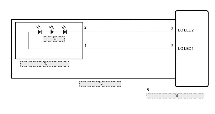
| *a | Lo / Hi Beam |
| *b | Headlight LED Unit Assembly |
| *c | Headlight Unit Assembly |
| *d | No. 1 Headlight ECU Sub-assembly |
CAUTION / NOTICE / HINT
Note
If the No. 1 headlight ECU sub-assembly LH has been replaced, it is necessary to synchronize the vehicle information.
PROCEDURE
-
CHECK FOR DTC
-
Clear the DTCs.
Body Electrical > HL AutoLeveling > Clear DTCs
Body Electrical > HL AutoLeveling (Sub) > Clear DTCs -
10 seconds elapse after turning the engine switch on (IG) and illuminating the low beam headlights using the light control switch.
-
Check for DTCs.
Body Electrical > HL AutoLeveling > Trouble Codes
Body Electrical > HL AutoLeveling (Sub) > Trouble CodesOK DTC B2439 and B243A are not output. Result Result Proceed to OK A NG (DTC B2439 is output) B NG (DTC B243A is output) C
A 
USE SIMULATION METHOD TO CHECK Click here
C 
CHECK HEADLIGHT UNIT ASSEMBLY RH Click here
B 
-
-
CHECK HEADLIGHT UNIT ASSEMBLY LH
-
Interchange the headlight unit assembly LH with RH and connect the connectors to them.
-
Clear the DTCs.
Body Electrical > HL AutoLeveling > Clear DTCs
Body Electrical > HL AutoLeveling (Sub) > Clear DTCs -
10 seconds elapse after turning the engine switch on (IG) and illuminating the low beam headlights using the light control switch.
-
Check for DTCs.
Body Electrical > HL AutoLeveling > Trouble Codes
Body Electrical > HL AutoLeveling (Sub) > Trouble CodesResult Result Proceed to DTC B2439 is output A DTC B243A is output B
A
REPLACE NO. 1 HEADLIGHT ECU SUB-ASSEMBLY LH Click here
B
-
-
CHECK HEADLIGHT UNIT ASSEMBLY LH
-
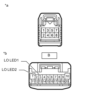
*a Component without harness connected
(Headlight LED Unit Assembly LH)
*b Component without harness connected
(No. 1 Headlight ECU Sub-assembly LH)
Remove the headlight unit assembly LH.
-
Remove the headlight LED unit assembly LH.
-
Measure the resistance according to the value(s) in the table below.
Standard Resistance Tester Connection Condition Specified Condition 2 - B-2 (LO LED2) Always Below 1 Ω 1 - B-3 (LO LED1) Always Below 1 Ω Result Proceed to OK NG
OK
REPLACE HEADLIGHT LED UNIT ASSEMBLY LH Click here
NG
REPLACE HEADLIGHT UNIT ASSEMBLY LH Click here
-
-
CHECK HEADLIGHT UNIT ASSEMBLY RH
-
Interchange the headlight unit assembly RH with LH and connect the connectors to them.
-
Clear the DTCs.
Body Electrical > HL AutoLeveling > Clear DTCs
Body Electrical > HL AutoLeveling (Sub) > Clear DTCs -
10 seconds elapse after turning the engine switch on (IG) and illuminating the low beam headlights using the light control switch.
-
Check for DTCs.
Body Electrical > HL AutoLeveling > Trouble Codes
Body Electrical > HL AutoLeveling (Sub) > Trouble CodesResult Result Proceed to DTC B243A is output A DTC B2439 is output B
A
REPLACE NO. 1 HEADLIGHT ECU SUB-ASSEMBLY RH Click here
B
-
-
CHECK HEADLIGHT UNIT ASSEMBLY RH
-
*a Component without harness connected
(Headlight LED Unit Assembly RH)
*b Component without harness connected
(No. 1 Headlight ECU Sub-assembly RH)
Remove the headlight unit assembly RH.
-
Remove the headlight LED unit assembly RH.
-
Measure the resistance according to the value(s) in the table below.
Standard Resistance Tester Connection Condition Specified Condition 2 - B-2 (LO LED2) Always Below 1 Ω 1 - B-3 (LO LED1) Always Below 1 Ω Result Proceed to OK NG
OK
REPLACE HEADLIGHT LED UNIT ASSEMBLY RH Click here
NG
REPLACE HEADLIGHT UNIT ASSEMBLY RH Click here
-