FRONT WIPER MOTOR INSTALLATION
CAUTION / NOTICE / HINT
Note
The front wiper motor does not have a link mechanism. Therefore, take care not to slide it out of position when removing or installing the front wiper arm.
Tech Tips
-
Use the same procedure for RHD and LHD vehicles.
-
The procedure listed below is for LHD vehicles.
PROCEDURE
-
INSTALL WINDSHIELD WIPER MOTOR ASSEMBLY
-
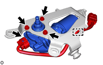
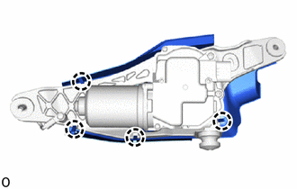
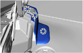
Install the windshield wiper motor assembly to the wiper bracket assembly with the 3 screws.
- Torque:
- 5.4 N*m { 55 kgf*cm, 48 in.*lbf }
-
Connect the connector and attach the clamp.
-
-
INSTALL NO. 1 WINDSHIELD WIPER SHAFT COVER
-
Attach the claws and install the No. 1 windshield wiper shaft cover.
-
-
INSTALL FRONT WIPER MOTOR AND BRACKET ASSEMBLY
-
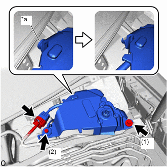
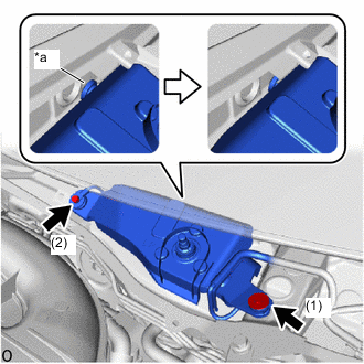
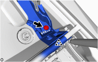
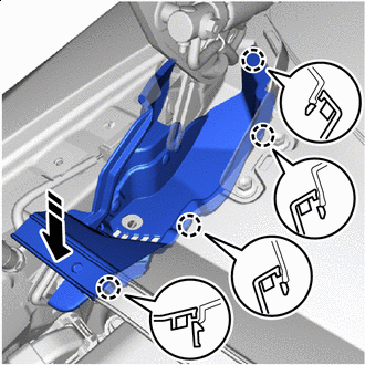
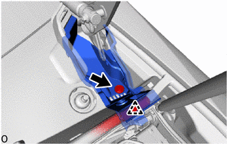
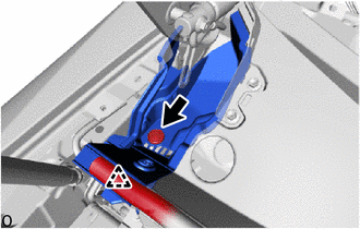
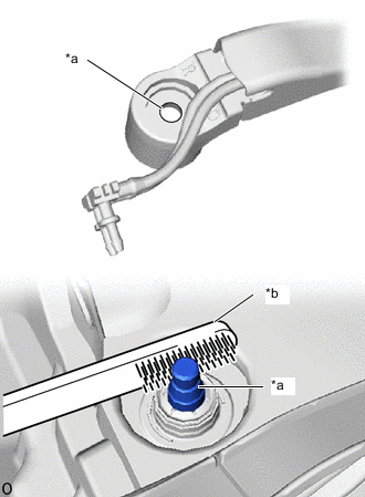
*a Grommet Attach the grommet and temporarily install the front wiper motor and bracket assembly as shown in the illustration.
-
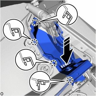
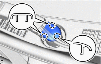
Temporarily install the front wiper motor and bracket assembly with the 2 bolts.
-
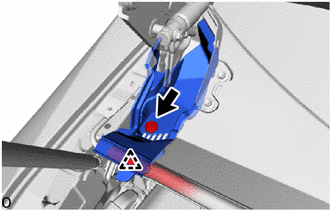
Tighten the 2 bolts in the order shown in the illustration.
- Torque:
- 5.5 N*m { 56 kgf*cm, 49 in.*lbf }
-
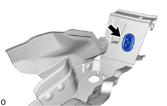
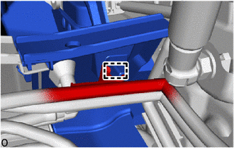
Connect the connector.
-
-
INSTALL FRONT WIPER MOTOR COVER
-
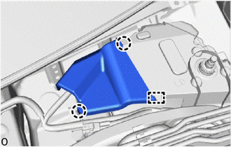
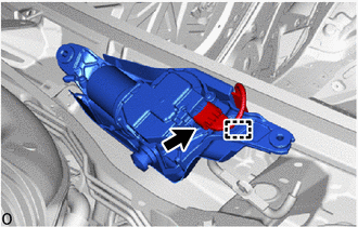
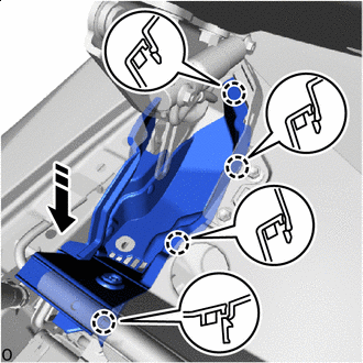
Attach the guide and claws to install the front wiper motor cover.
-
-
INSTALL NO. 2 WINDSHIELD WIPER MOTOR ASSEMBLY
-
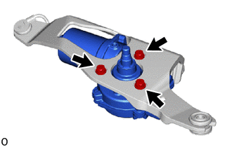
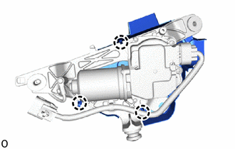
Install the No. 2 windshield wiper motor assembly to the wiper bracket assembly with the 3 screws.
- Torque:
- 5.4 N*m { 55 kgf*cm, 48 in.*lbf }
-
-
INSTALL NO. 2 WINDSHIELD WIPER SHAFT COVER
-
Attach the claws to install the No. 2 windshield wiper shaft cover.
-
-
INSTALL NO. 2 FRONT WIPER MOTOR AND BRACKET ASSEMBLY
-
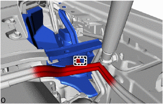
Connect the connector and attach the clamp.
-
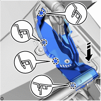
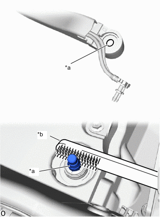
*a Grommet Attach the grommet and temporarily install the No. 2 front wiper motor and bracket assembly as shown in the illustration.
-
Temporarily install the No. 2 front wiper motor and bracket assembly with the 2 bolts.
-
Tighten the 2 bolts in the order shown in the illustration.
- Torque:
- 5.5 N*m { 56 kgf*cm, 49 in.*lbf }
-
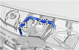
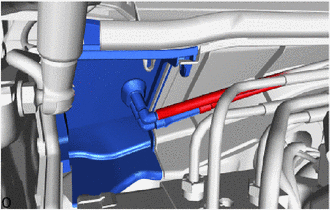
Attach the clamps.
-
-
INSTALL HOOD TO COWL TOP SEAL
-
Attach the clips to install the hood to cowl top seal.
-
-
INSTALL WASHER HOSE ASSEMBLY (for LHD)
-
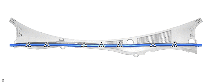
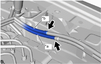
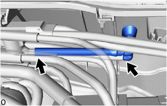
Attach the clamps to install the washer hose assembly.
-
Connect the washer hose assembly to the washer grommet.

Grommet - -
-
-
INSTALL WASHER HOSE ASSEMBLY (for RHD)
-
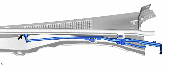
Connect the washer hose assembly to the guide.
-
Attach the clamps to install the washer hose assembly.
-
Connect the washer hose assembly to the washer grommet.
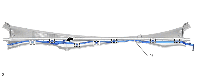
*a Guide - - Grommet - -
-
-
INSTALL COWL TOP VENTILATOR LOUVER SUB-ASSEMBLY
-
*a Main Nozzle Side *b Sub Nozzle Side Connect the 2 washer hoses.
-
Turn the front side of the cowl top ventilator louver sub-assembly as shown in the illustration and temporarily install it.
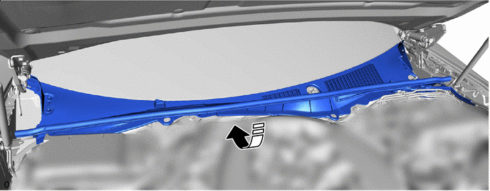

Install in this Direction - - -
Align the positioning guide of the cowl top ventilator louver sub-assembly to the cutout of the front window inner center moulding.
-
Hold the rear side of the cowl top ventilator louver sub-assembly and attach it to the front window inner center moulding.
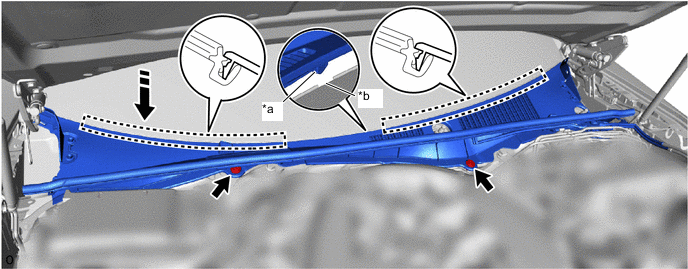
*a Guide *b Notch Install in this Direction - - Tech Tips
-
Check that the cowl top ventilator louver sub-assembly is not loose.
-
Check that the positioning guide is not pinched by the front window inner center moulding.
-
-
Install the 2 clips.
-
-
INSTALL CENTER COWL TOP VENTILATOR LOUVER
-
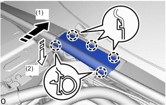
Install in this Direction (1) 
Install in this Direction (2) Attach the claws to install the center cowl top ventilator louver as shown in the illustration.
-
-
INSTALL WASHER GROMMET
-
Install the washer grommet.
Tech Tips
Use the same procedure for the other side.
-
-
INSTALL NO. 3 COWL TOP PANEL INSULATOR (for LHD)
-
Install in this Direction Attach the claws to install the No. 3 cowl top panel insulator.
-
Install the clip.
-
Install the clip of the hood to cowl top seal.
-
Connect the 2 washer hoses.
-
Attach the clamp.
-
-
INSTALL NO. 2 COWL TOP PANEL INSULATOR (for LHD)
-
Install in this Direction Attach the claws to install the No. 2 cowl top panel insulator.
-
Install the clip.
-
Install the clip of the hood to cowl top seal.
-
-
INSTALL NO. 3 COWL TOP PANEL INSULATOR (for RHD)
-
Install in this Direction Attach the claws to install the No. 3 cowl top panel insulator.
-
Install the clip.
-
Install the clip of the hood to cowl top seal.
-
Attach the clamp.
-
-
INSTALL NO. 2 COWL TOP PANEL INSULATOR (for RHD)
-
Connect the 2 washer hose as shown in the illustration.
-
Install in this Direction Attach the claws and install the No. 2 cowl top panel insulator.
-
Install the clip.
-
Install the clip of the hood to cowl top seal.
-
-
INSTALL ROOF DRIP SIDE FINISH MOULDING RH
-
Attach the claws to install the roof drip side finish moulding RH.
-
-
INSTALL ROOF DRIP SIDE FINISH MOULDING LH
Tech Tips
Use the same procedure described for the RH side.
-
INSTALL FRONT FENDER REINFORCEMENT TOP SUB-ASSEMBLY LH
-
INSTALL FRONT FENDER REINFORCEMENT TOP SUB-ASSEMBLY RH
Tech Tips
Use the same procedure described for the LH side.
-
INSTALL LOWER RADIATOR AIR DEFLECTOR
-
INSTALL RADIATOR SUPPORT TO FRAME SEAL RH
-
INSTALL RADIATOR SUPPORT TO FRAME SEAL LH
-
CONNECT CABLE TO NEGATIVE BATTERY TERMINAL
Note
Front wiper arm installation is performed with the engine switch on (IG). Therefore, pay attention to the battery level.
-
INSTALL WINDSHIELD WIPER ARM AND BLADE ASSEMBLY RH (for LHD)
-
When reinstalling:
-
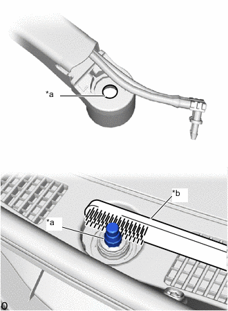
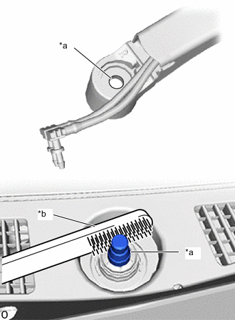
*a Serrations *b Wire Brush Clean the wiper arm serrations.
Note
Do not grind the wiper arm serrations excessively.
-
-
Using a wire brush, clean the serrations of the No. 2 windshield wiper motor assembly.
-
When not using the GTS:
-
Turn the engine switch on (IG).
Note
Automatic position calibration for the windshield wiper motor assembly and No. 2 windshield wiper motor assembly is performed via LIN communication. Therefore, do not turn the engine switch on (IG) with only one side connected.
-
Operate the windshield wiper motor assembly and stop it at the automatic stop position.
-
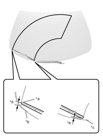
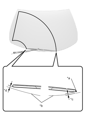
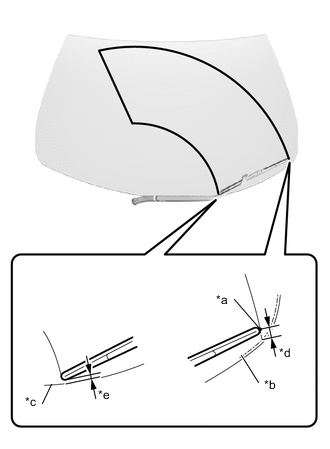
*a Ceramic Dot *b Moulding Lip Line *c Windshield Glass Edge *d 4.5 to 24.5 mm (0.177 to 0.965 in.) *e 14.3 mm (0.563 in.) Install the windshield wiper arm and blade assembly RH with the nut to the position shown in the illustration.
- Torque:
- 22 N*m { 224 kgf*cm, 16 ft.*lbf }
Tech Tips
Perform work from directly above so that the No. 2 windshield wiper motor assembly does not rotate when installing the nut.
-
Turn the engine switch off.
-
-
When using the GTS:
-
Turn the engine switch off.
-
Connect the GTS to the DLC3.
-
Turn the engine switch on (IG).
Note
Automatic position calibration for the windshield wiper motor assembly and No. 2 windshield wiper motor assembly is performed via LIN communication. Therefore, do not turn the engine switch on (IG) with only one side connected.
-
Turn the GTS on.
-
According to the display on the GTS, display the utility screen by selecting "Main Body"" → "Utility".
-
Select and perform "Wiper Arm Installation".
Body Electrical > Main Body > UtilityTester Display Wiper Arm Installation Note
-
When performing "Wiper Arm Installation", perform work according to the instructions displayed on the GTS display.
-
If the instructions displayed on the GTS are not followed correctly, perform this procedure from the beginning again.
Tech Tips
When performing "Wiper Arm Installation" the wiper arm will wipe 1 time due to the set initial position.
-
-
*a Ceramic Dot *b Moulding Lip Line *c Windshield Glass Edge *d 4.5 to 24.5 mm (0.177 to 0.965 in.) *e 14.3 mm (0.563 in.) Install the windshield wiper arm and blade assembly RH with the nut to the position shown in the illustration.
- Torque:
- 22 N*m { 224 kgf*cm, 16 ft.*lbf }
-
Turn the engine switch off.
-
Disconnect the GTS.
-
-
Connect the 2 washer hoses.
-
Operate the windshield wiper motor assembly while spraying washer fluid or water onto the windshield glass and check that the front wiper blade wipes properly and does not interfere with the body.
-
Lift up the windshield wiper arm 2 times and check that the end of the front wiper blade is positioned as shown in the illustration.
Tech Tips
If the windshield wiper arm and blade assembly RH is not in the specified position, install it again.
-
-
INSTALL WINDSHIELD WIPER ARM AND BLADE ASSEMBLY RH (for RHD)
-
When reinstalling:
-
*a Serrations *b Wire Brush Clean the wiper arm serrations.
Note
Do not grind the wiper arm serrations excessively.
-
-
Using a wire brush, clean the serrations of the No. 2 windshield wiper motor assembly.
-
When not using the GTS:
-
Turn the engine switch on (IG).
Note
Automatic position calibration for the windshield wiper motor assembly and No. 2 windshield wiper motor assembly is performed via LIN communication. Therefore, do not turn the engine switch on (IG) with only one side connected.
-
Operate the windshield wiper motor assembly and stop it at the automatic stop position.
-
*a Ceramic Dot *b Moulding Lip Line *c 4.5 to 24.5 mm (0.177 to 0.965 in.) *d 15.2 mm (0.598 in.) Install the windshield wiper arm and blade assembly RH with the nut to the position shown in the illustration.
- Torque:
- 22 N*m { 224 kgf*cm, 16 ft.*lbf }
Tech Tips
Perform work from directly above so that the windshield wiper motor assembly does not rotate when installing the nut.
-
Turn the engine switch off.
-
-
When using the GTS:
-
Turn the engine switch off.
-
Connect the GTS to the DLC3.
-
Turn the engine switch on (IG).
Note
Automatic position calibration for the windshield wiper motor assembly and No. 2 windshield wiper motor assembly is performed via LIN communication. Therefore, do not turn the engine switch on (IG) with only one side connected.
-
Turn the GTS on.
-
According to the display on the GTS, display the utility screen by selecting "Main Body"" → "Utility".
-
Select and perform "Wiper Arm Installation".
Body Electrical > Main Body > UtilityTester Display Wiper Arm Installation Note
-
When performing "Wiper Arm Installation", perform work according to the instructions displayed on the GTS display.
-
If the instructions displayed on the GTS are not followed correctly, perform this procedure from the beginning again.
Tech Tips
When performing "Wiper Arm Installation" the wiper arm will wipe 1 time due to the set initial position.
-
-
*a Ceramic Dot *b Moulding Lip Line *c 4.5 to 24.5 mm (0.177 to 0.965 in.) *d 15.2 mm (0.598 in.) Install the windshield wiper arm and blade assembly RH with the nut to the position shown in the illustration.
- Torque:
- 22 N*m { 224 kgf*cm, 16 ft.*lbf }
-
Turn the engine switch off.
-
Disconnect the GTS.
-
-
Connect the 2 washer hoses.
-
Operate the windshield wiper motor assembly while spraying washer fluid or water onto the windshield glass and check that the front wiper blade wipes properly and does not interfere with the body.
-
Lift up the windshield wiper arm 2 times and check that the end of the front wiper blade is positioned as shown in the illustration.
Tech Tips
If the windshield wiper arm and blade assembly RH is not in the specified position, install it again.
-
-
INSTALL WINDSHIELD WIPER ARM AND BLADE ASSEMBLY LH (for LHD)
-
When reinstalling:
-
*a Serrations *b Wire Brush Clean the wiper arm serrations.
Note
Do not grind the wiper arm serrations excessively.
-
-
Using a wire brush, clean the serrations of the windshield wiper motor assembly.
-
When not using the GTS:
-
Turn the engine switch on (IG).
Note
Automatic position calibration for the windshield wiper motor assembly and No. 2 windshield wiper motor assembly is performed via LIN communication. Therefore, do not turn the engine switch on (IG) with only one side connected.
-
Operate the windshield wiper motor assembly and stop it at the automatic stop position.
-
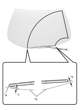
*a Ceramic Dot *b Windshield Glass Edge *c 4.5 to 24.5 mm (0.177 to 0.965 in.) *d 15.2 mm (0.598 in.) Install the windshield wiper arm and blade assembly LH with the nut to the position shown in the illustration.
- Torque:
- 22 N*m { 224 kgf*cm, 16 ft.*lbf }
Tech Tips
Perform work from directly above so that the windshield wiper motor assembly does not rotate when installing the nut.
-
Turn the engine switch off.
-
-
When using the GTS:
-
Turn the engine switch off.
-
Connect the GTS to the DLC3.
-
Turn the engine switch on (IG).
Note
Automatic position calibration for the windshield wiper motor assembly and No. 2 windshield wiper motor assembly is performed via LIN communication. Therefore, do not turn the engine switch on (IG) with only one side connected.
-
Turn the GTS on.
-
According to the display on the GTS, display the utility screen by selecting "Main Body"" → "Utility".
-
Select and perform "Wiper Arm Installation".
Body Electrical > Main Body > UtilityTester Display Wiper Arm Installation Note
-
When performing "Wiper Arm Installation", perform work according to the instructions displayed on the GTS display.
-
If the instructions displayed on the GTS are not followed correctly, perform this procedure from the beginning again.
Tech Tips
When performing "Wiper Arm Installation" the wiper arm will wipe 1 time due to the set initial position.
-
-
*a Ceramic Dot *b Windshield Glass Edge *c 4.5 to 24.5 mm (0.177 to 0.965 in.) *d 15.2 mm (0.598 in.) Install the windshield wiper arm and blade assembly RH with the nut to the position shown in the illustration.
- Torque:
- 22 N*m { 224 kgf*cm, 16 ft.*lbf }
-
Turn the engine switch off.
-
Disconnect the GTS.
-
-
Connect the 2 washer hoses.
-
Operate the windshield wiper motor assembly while spraying washer fluid or water onto the windshield glass and check that the front wiper blade wipes properly and does not interfere with the body.
-
Lift up the windshield wiper arm 2 times and check that the end of the front wiper blade is positioned as shown in the illustration.
Tech Tips
If the windshield wiper arm and blade assembly LH is not in the specified position, install it again.
-
-
INSTALL WINDSHIELD WIPER ARM AND BLADE ASSEMBLY LH (for RHD)
-
When reinstalling:
-
*a Serrations *b Wire Brush Clean the wiper arm serrations.
Note
Do not grind the wiper arm serrations excessively.
-
-
Using a wire brush, clean the serrations of the windshield wiper motor assembly.
-
When not using the GTS:
-
Turn the engine switch on (IG).
Note
Automatic position calibration for the windshield wiper motor assembly and No. 2 windshield wiper motor assembly is performed via LIN communication. Therefore, do not turn the engine switch on (IG) with only one side connected.
-
Operate the windshield wiper motor assembly and stop it at the automatic stop position.
-
*a Ceramic Dot *b Moulding Lip Line *c Windshield Glass Edge *d 4.5 to 24.5 mm (0.177 to 0.965 in.) *e 14.3 mm (0.563 in.) Install the windshield wiper arm and blade assembly LH with the nut to the position shown in the illustration.
- Torque:
- 22 N*m { 224 kgf*cm, 16 ft.*lbf }
Tech Tips
Perform work from directly above so that the No. 2 windshield wiper motor assembly does not rotate when installing the nut.
-
Turn the engine switch off.
-
-
When using the GTS:
-
Turn the engine switch off.
-
Connect the GTS to the DLC3.
-
Turn the engine switch on (IG).
Note
Automatic position calibration for the windshield wiper motor assembly and No. 2 windshield wiper motor assembly is performed via LIN communication. Therefore, do not turn the engine switch on (IG) with only one side connected.
-
Turn the GTS on.
-
According to the display on the GTS, display the utility screen by selecting "Main Body"" → "Utility".
-
Select and perform "Wiper Arm Installation".
Body Electrical > Main Body > UtilityTester Display Wiper Arm Installation Note
-
When performing "Wiper Arm Installation", perform work according to the instructions displayed on the GTS display.
-
If the instructions displayed on the GTS are not followed correctly, perform this procedure from the beginning again.
Tech Tips
When performing "Wiper Arm Installation" the wiper arm will wipe 1 time due to the set initial position.
-
-
*a Ceramic Dot *b Moulding Lip Line *c Windshield Glass Edge *d 4.5 to 24.5 mm (0.177 to 0.965 in.) *e 14.3 mm (0.563 in.) Install the windshield wiper arm and blade assembly RH with the nut to the position shown in the illustration.
- Torque:
- 22 N*m { 224 kgf*cm, 16 ft.*lbf }
-
Turn the engine switch off.
-
Disconnect the GTS.
-
-
Connect the 2 washer hoses.
-
Operate the windshield wiper motor assembly while spraying washer fluid or water onto the windshield glass and check that the front wiper blade wipes properly and does not interfere with the body.
-
Lift up the windshield wiper arm 2 times and check that the end of the front wiper blade is positioned as shown in the illustration.
Tech Tips
If the windshield wiper arm and blade assembly LH is not in the specified position, install it again.
-
-
INSTALL FRONT WIPER ARM HEAD CAP
-
Attach the claws and install the front wiper arm head cap.
Tech Tips
Use the same procedure for the other side.
-
-
INSPECT WASHER NOZZLE
-
Check the position that the washer fluid hits the windshield.
-
Check that there are no washer spray fluid leaks from any of the connectors of the washer hoses.
-