WIPER AND WASHER SYSTEM, Diagnostic DTC:B1372
| DTC Code | DTC Name |
|---|---|
| B1372 | Wiper Switch Signal Mismatch between LIN and Line |
DESCRIPTION
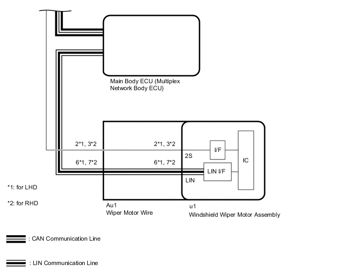
Under normal operation, the windshield wiper motor assembly receives operation signals from the windshield wiper switch assembly via LIN communication.
The windshield wiper motor assembly and windshield wiper switch assembly are also connected via direct line in order to operate the front wipers in HI in an emergency. If the operation signals sent via LIN communication and direct line do not match, this DTC is stored.
| DTC No. | Detection Item | DTC Detection Condition | Trouble Area | Memory | DTC Output from |
|---|---|---|---|---|---|
| B1372 | Wiper Switch Signal Mismatch between LIN and Line |
DTC Detection Condition:
Malfunction Condition:
Malfunction Duration: |
|
○ | Windshield wiper motor assembly |
WIRING DIAGRAM
-
for LH Side:

-
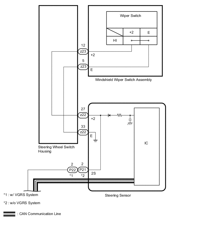
for RH Side:
CAUTION / NOTICE / HINT
Note
First perform the communication function inspections in How to Proceed with Troubleshooting to confirm that there are no CAN communication malfunctions before troubleshooting this problem.
PROCEDURE
-
CHECK FOR DTC
-
Clear the DTC.
Body Electrical > Wiper > Clear DTCs -
Turn the engine switch on (IG) and wait for at least 10 seconds.
-
Check for DTC.
Body Electrical > Wiper > Trouble CodesOK DTC B1372 is not output Result Proceed to OK NG
OK 
USE SIMULATION METHOD TO CHECK Click here
NG 
-
-
READ VALUE USING GTS
-
Read the Data List according to the display on the GTS.
Body Electrical > Wiper > Data ListTester Display Measurement Item Range Normal Condition Diagnostic Note Wiper Switch HI (Line) Windshield wiper switch assembly HI signal (abnormal control system) input condition OFF or ON OFF: Windshield wiper switch assembly not in HI position
ON: Windshield wiper switch assembly in HI position
-
Chassis > Steering Angle Sensor > Data ListTester Display Measurement Item Range Normal Condition Diagnostic Note Wiper Hi Switch Windshield wiper switch assembly (HI position) condition OFF or ON OFF: Windshield wiper switch assembly not in HI position
ON: Windshield wiper switch assembly in HI position
-
Body Electrical > Wiper > Data ListTester Display Wiper Switch HI (Line)
Chassis > Steering Angle Sensor > Data ListTester Display Wiper Hi Switch Result Result Proceed to Only "Wiper Switch HI (Line)" changes normally A Only "Wiper Hi Switch" changes normally B
A
REPLACE STEERING SENSOR Click here
B
-
-
CHECK HARNESS AND CONNECTOR (WINDSHIELD WIPER MOTOR ASSEMBLY HI SIGNAL INPUT)
-
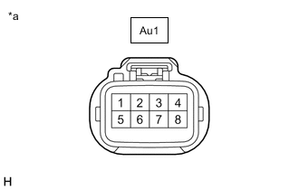
*a Front view of wire harness connector
(to Wiper Motor Wire)
Disconnect the wiper motor wire connector.
-
Measure the voltage according to the value(s) in the table below.
Standard Voltage for LHD Tester Connection Condition Specified Condition Au1-2 - Body ground Engine switch on (IG), HI operating Below 1 V Engine switch on (IG), Windshield wiper motor assembly stopped 11 to 14 V for RHD Tester Connection Condition Specified Condition Au1-3 - Body ground Engine switch on (IG), HI operating Below 1 V Engine switch on (IG), Windshield wiper motor assembly stopped 11 to 14 V Result Proceed to OK NG
NG 
CHECK HARNESS AND CONNECTOR (STEERING SENSOR - WIPER MOTOR WIRE) Click here
OK
-
-
INSPECT WIPER MOTOR WIRE
-
Remove the wiper motor wire.
-
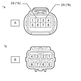
*A for LHD *B for RHD *a Windshield Wiper Motor Assembly Side *b Wire Harness Side Measure the resistance according to the value(s) in the table below.
Standard Resistance for LHD Tester Connection Condition Specified Condition A-2 (2S) - B-2 Always Below 1 Ω for RHD Tester Connection Condition Specified Condition A-3 (2S) - B-3 Always Below 1 Ω Result Proceed to OK NG
OK
REPLACE WINDSHIELD WIPER MOTOR ASSEMBLY Click here
NG
REPLACE WIPER MOTOR WIRE Click here
-
-
CHECK HARNESS AND CONNECTOR (STEERING SENSOR - WIPER MOTOR WIRE)
-
Disconnect the P22*1 or P21*2 steering sensor connector.
-
*1: w/ VGRS System
-
*2: w/o VGRS System
-
-
Disconnect the Au1 wiper motor wire connector.
-
Measure the resistance according to the value(s) in the table below.
Standard Resistance w/ VGRS System, for LHD Tester Connection Condition Specified Condition P22-2 (2S) - Au1-2 Always Below 1 Ω P22-2 (2S) or Au1-2 - Body ground Always 10 kΩ or higher w/o VGRS System, for LHD Tester Connection Condition Specified Condition P21-2 (2S) - Au1-2 Always Below 1 Ω P21-2 (2S) or Au1-2 - Body ground Always 10 kΩ or higher w/ VGRS System, for RHD Tester Connection Condition Specified Condition P22-2 (2S) - Au1-3 Always Below 1 Ω P22-2 (2S) or Au1-3 - Body ground Always 10 kΩ or higher w/o VGRS System, for RHD Tester Connection Condition Specified Condition P21-2 (2S) - Au1-3 Always Below 1 Ω P21-2 (2S) or Au1-3 - Body ground Always 10 kΩ or higher Result Proceed to OK NG
OK
REPLACE STEERING SENSOR Click here
NG
REPAIR OR REPLACE HARNESS OR CONNECTOR
-