WIPER AND WASHER SYSTEM TERMINALS OF ECU
-
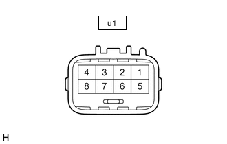
CHECK WINDSHIELD WIPER MOTOR ASSEMBLY
Tech Tips
Since the windshield wiper motor assembly uses waterproof connectors, the voltage, resistance and waveform cannot be checked directly. The voltage, resistance and waveform are indicated for reference only.
-
Measure the voltage, resistance and waveform on the wire harness side connector according to the value(s) in the table below.
for LHD Terminal No. (Symbol) Wiring Color Terminal Description Condition Specified Condition u1-4 (WSR+) - Body ground L - Body ground Washer motor operation signal Windshield washer motor and pump assembly not operating Below 1 V Windshield washer motor and pump assembly operating 11 to 14 V u1-3 (WSR-) - Body ground L-W - Body ground Washer motor operation signal Windshield washer motor and pump assembly not operating Below 1 V Windshield washer motor and pump assembly operating 11 to 14 V u1-2 (2S) - Body ground B - Body ground Wiper HI operation signal Windshield wiper motor assembly not operating 11 to 14 V Windshield wiper motor assembly HI operating Below 1 V u1-1 (GND) - Body ground W-B - Body ground Ground Always Below 1 Ω u1-8 (FWAB) - Body ground W-R - Body ground Washer motor power supply Engine switch on (IG) 11 to 14 V Engine switch off Below 1 V u1-7 (+B) - Body ground W - Body ground Wiper motor power supply Engine switch on (IG) or within approximately 60 seconds of engine switch being turned off 11 to 14 V Approximately 60 seconds have elapsed after engine switch is turned off Below 1 V u1-6 (LIN) - Body ground R - Body ground LIN communication signal Engine switch on (IG) Pulse generation Engine switch off Below 1 V u1-5 (LLIN) - Body ground G - Body ground LIN communication signal Engine switch on (IG) Pulse generation Engine switch off Below 1 V for RHD Terminal No. (Symbol) Wiring Color Terminal Description Condition Specified Condition u1-1 (WSR+) - Body ground L - Body ground Washer motor operation signal Windshield washer motor and pump assembly not operating Below 1 V Windshield washer motor and pump assembly operating 11 to 14 V u1-2 (WSR-) - Body ground L-W - Body ground Washer motor operation signal Windshield washer motor and pump assembly not operating Below 1 V Windshield washer motor and pump assembly operating 11 to 14 V u1-3 (2S) - Body ground B - Body ground Wiper HI operation signal Windshield wiper motor assembly not operating 11 to 14 V Windshield wiper motor assembly HI operating Below 1 V u1-4 (GND) - Body ground W-B - Body ground Ground Always Below 1 Ω u1-5 (FWAB) - Body ground W-R - Body ground Washer motor power supply Engine switch on (IG) 11 to 14 V Engine switch off Below 1 V u1-6 (+B) - Body ground W - Body ground Wiper motor power supply Engine switch on (IG) or within approximately 60 seconds of engine switch being turned off 11 to 14 V Approximately 60 seconds have elapsed after engine switch is turned off Below 1 V u1-7 (LIN) - Body ground R - Body ground LIN communication signal Engine switch on (IG) Pulse generation Engine switch off Below 1 V u1-8 (LLIN) - Body ground G - Body ground LIN communication signal Engine switch on (IG) Pulse generation Engine switch off Below 1 V
-
-
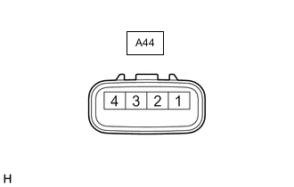
CHECK NO. 2 WINDSHIELD WIPER MOTOR ASSEMBLY
Tech Tips
Since the No. 2 windshield wiper motor assembly uses waterproof connectors, the voltage, resistance and waveform cannot be checked directly. The voltage, resistance and waveform are indicated for reference only.
-
Measure the voltage, resistance and waveform on the wire harness side connector according to the value(s) in the table below.
for LHD Terminal No. (Symbol) Wiring Color Terminal Description Condition Specified Condition A44-4 (+B) - Body ground R - Body ground Wiper motor power supply Engine switch on (IG) or within approximately 60 seconds of engine switch being turned off 11 to 14 V Approximately 60 seconds have elapsed after engine switch is turned off Below 1 V A44-2 (LIN) - Body ground SB - Body ground LIN communication signal Engine switch on (IG) Pulse generation Engine switch off Below 1 V A44-1 (GND) - Body ground W-B - Body ground Ground Always Below 1 Ω for RHD Terminal No. (Symbol) Wiring Color Terminal Description Condition Specified Condition A44-1 (+B) - Body ground R - Body ground Wiper motor power supply Engine switch on (IG) or within approximately 60 seconds of engine switch being turned off 11 to 14 V Approximately 60 seconds have elapsed after engine switch is turned off Below 1 V A44-3 (LIN) - Body ground SB - Body ground LIN communication signal Engine switch on (IG) Pulse generation Engine switch off Below 1 V A44-4 (GND) - Body ground W-B - Body ground Ground Always Below 1 Ω
-
-
CHECK DRIVER SIDE JUNCTION BLOCK ASSEMBLY AND MAIN BODY ECU (MULTIPLEX NETWORK BODY ECU)
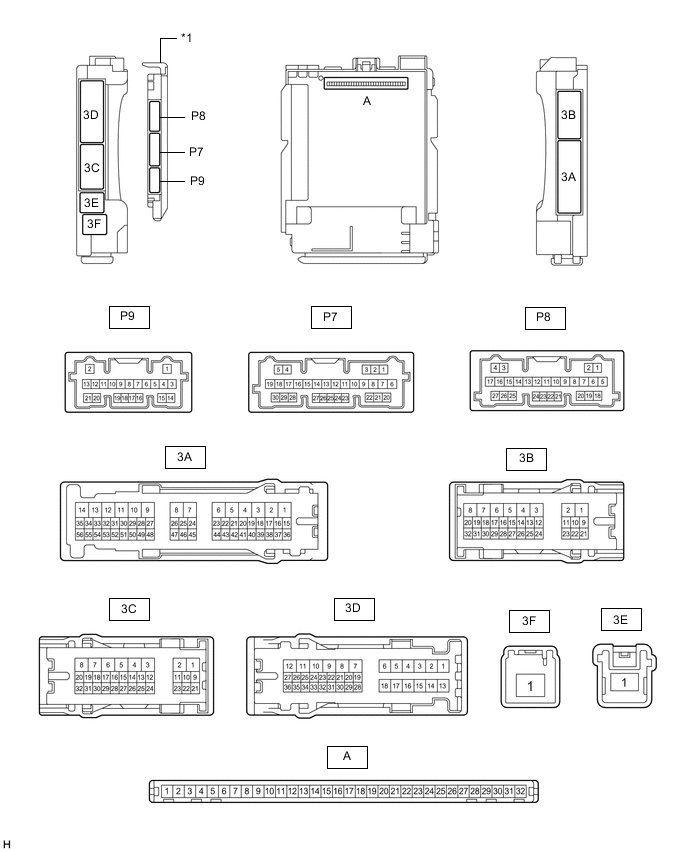
*1 Main Body ECU (Multiplex Network Body ECU) - -
-
Remove the main body ECU (multiplex network body ECU) from the driver side junction block assembly.
-
Measure the voltage and resistance according to the value(s) in the table below.
Terminal No. (Symbol) Wiring Color Terminal Description Condition Specified Condition A-11 (GND) - Body ground None - Body ground Ground Always Below 1 Ω A-30 (ACC) - Body ground None - Body ground ACC power supply Engine switch off Below 1 V Engine switch on (ACC) 11 to 14 V A-31 (BECU) - Body ground None - Body ground Battery power supply Always 11 to 14 V A-32 (IG) - Body ground None - Body ground IG power supply Engine switch on (IG) 11 to 14 V Engine switch off Below 1 V -
Install the main body ECU (multiplex network body ECU) to the driver side junction block assembly.
-
Measure the voltage according to the value(s) in the table below.
Terminal No. (Symbol) Wiring Color Terminal Description Condition Specified Condition P7-21 (WPS) - Body ground LG - Body ground Windshield wiper switch relay (WIPER NO.1) power supply Engine switch on (IG) or within approximately 60 seconds of engine switch being turned off 11 to 14 V Approximately 60 seconds have elapsed after engine switch is turned off Below 1 V P7-22 (WPS2) - Body ground L - Body ground Windshield wiper switch relay (WIPER NO.2) power supply Engine switch on (IG) or within approximately 60 seconds of engine switch being turned off 11 to 14 V Approximately 60 seconds have elapsed after engine switch is turned off Below 1 V
-
-
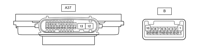
CHECK NO. 1 HEADLIGHT ECU SUB-ASSEMBLY RH
Tech Tips
Since the No. 1 headlight ECU sub-assembly RH uses waterproof connectors, the voltage, resistance and waveform cannot be checked directly. The voltage, resistance and waveform are indicated for reference only.
-
Measure the voltage and resistance on the wire harness side connector according to the value(s) in the table below.
Terminal No. (Symbol) Wiring Color Terminal Description Condition Specified Condition A37-4 (IG) - Body ground R - Body ground IG power supply Engine switch on (IG) 11 to 14 V Engine switch off Below 1 V A37-7 (HLC) - Body ground B - Body ground Headlight cleaner motor operation signal Engine switch on (IG), light control switch head and headlight cleaner motor not operating 11 to 14 V Engine switch on (IG), light control switch head and headlight cleaner operating Below 1 V A37-12 (GND) - Body ground BR - Body ground Ground Always Below 1 Ω A37-13 (ECUB) - Body ground R - Body ground Power supply Approximately 15 seconds elapsed after turning the engine switch off Below 1 V Engine switch on (IG) or within approximately 15 seconds of engine switch being turned off 11 to 14 V
-
-
CHECK COMBINATION METER ASSEMBLY
-
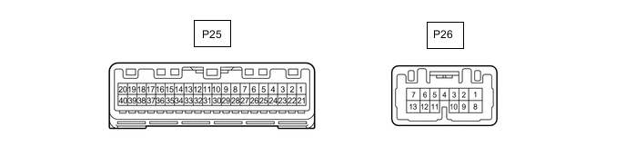
Disconnect the P25 combination meter assembly connector.
-
Measure the voltage and resistance according to the value(s) in the table below.
Terminal No. (Symbol) Wiring Color Terminal Description Condition Specified Condition P25-21 (IG+) - Body ground G - Body ground IG power supply Engine switch on (IG) 11 to 14 V Engine switch off Below 1 V P25-22 (B) - Body ground V - Body ground Battery power supply Always 11 to 14 V P25-31 (ES) - Body ground W-B - Body ground Body ground Always Below 1 Ω -
Reconnect the P25 combination meter assembly connector.
-
Measure the voltage according to the value(s) in the table below.
Terminal No. (Symbol) Wiring Color Terminal Description Condition Specified Condition P25-16 (WLVL) - Body ground V - Body ground Washer fluid level signal Engine switch on (IG), washer fluid level not low 11 to 14 V Engine switch on (IG), washer fluid level low Below 1 V -
Measure the waveform according to the value(s) in the table below.
Terminal No. (Symbol) Wiring Color Terminal Description Condition Specified Condition P25-19 (+S) - Body ground L - Body ground Speed signal for other system (Output) Driving at approximately 20 km/h (12 mph) Pulse generation (See waveform 1)
-
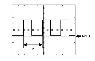
Waveform 1 (Reference):
Item Condition Tester Connection P25-19 (+S) - Body ground Tool Setting 5 V/DIV., 20 ms/DIV. Vehicle Condition Driving at approximately 20 km/h (12 mph) Tech Tips
When the system is functioning normally, one wheel revolution generates 4 pulses. As the vehicle speed increases, the width indicated by A in the illustration narrows.
-
-